2 System setup
20
Turning on the system
After making sure that you have properly set up the system and
connected all the required cables, you can now power on the system.
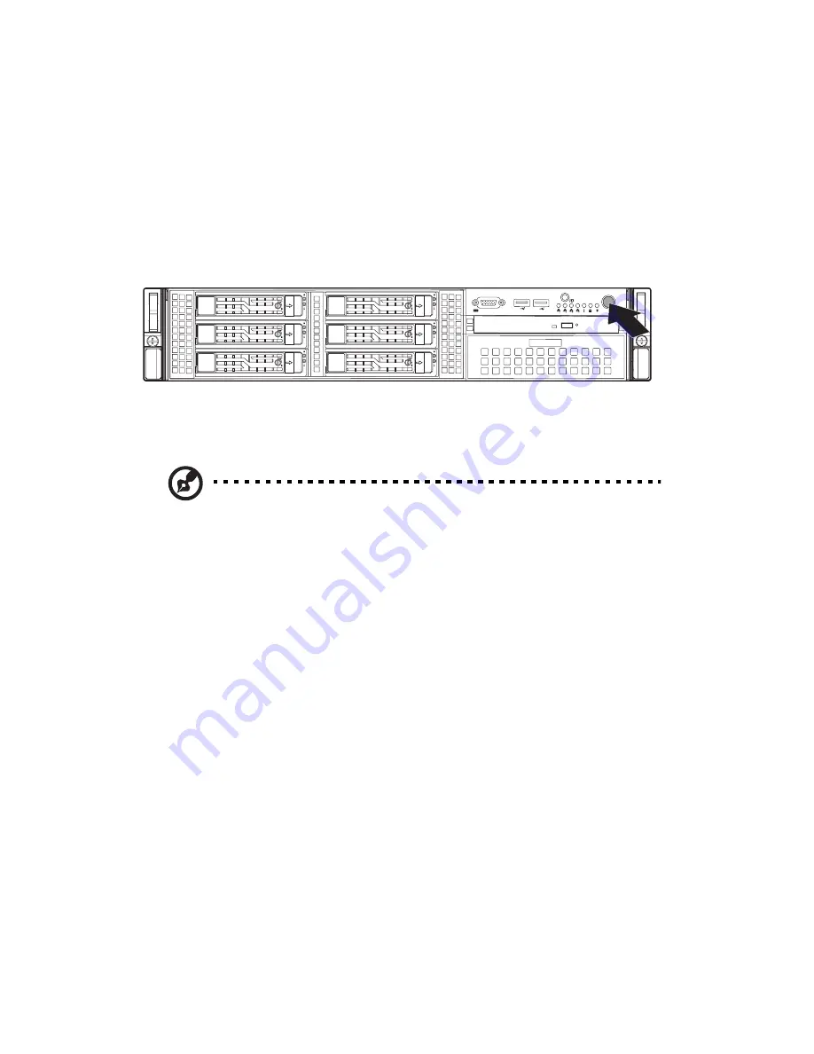
To power on the system:
After plugging in the power cord, press the power button.
The system starts up and displays a welcome message on the monitor.
After that, a series of POST messages appears. The POST messages
indicate if the system is running well or not.
Note: If the system does not turn on or boot after pressing the
power button(s), go to the next section for the possible causes of
the boot failure.
Aside from the POST messages, you can determine if the system is in
good condition by checking if the following occurred.
•
The power indicator on the front panel lights up green.
•
The Num Lock, Caps Lock, and Scroll Lock indicators on the
keyboard light up.
Power-on problems
If the system does not boot after you have applied power, check
thefollowing factors that might have caused the boot failure.
•
The external power cord may be loosely connected.
Check the power cord connection from the power source to the
power supply module AC input connector on the rear panel. Make
sure that the power cord is properly connected to the power
source and to the AC input connector.
•
No power comes from the grounded power outlet.
Summary of Contents for AR380 F1 Series
Page 1: ...AR380 F1 Series User Guide ...
Page 14: ...xiv ...
Page 18: ...xviii ...
Page 19: ...1 System tour ...
Page 35: ...2 System setup ...
Page 42: ...2 System setup 24 ...
Page 43: ...3 System upgrades ...
Page 82: ...3 System upgrades 64 ...
Page 83: ...4 System Bios ...
Page 119: ...101 View Event Log View the System Event Log Mark All Events as Read Marks all events as read ...
Page 120: ...4 System Bios 102 Clear Event Log This option clears the Event Log memory of all messages ...
Page 128: ...4 System Bios 110 are designed for maximum system stability but not for maximum performance ...
Page 129: ...5 System troubleshooting ...
Page 139: ...Appendix A Server management tools ...
Page 151: ...Appendix B Rack mount configuration ...
Page 152: ...Appendix B 134 ...
Page 163: ...Appendix C Acer Smart Console ...
Page 192: ...Appendix C Acer Smart Console 174 ...


