background image

104

Chapter 6

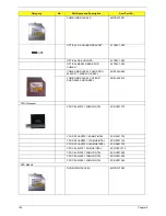
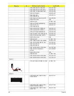
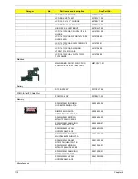
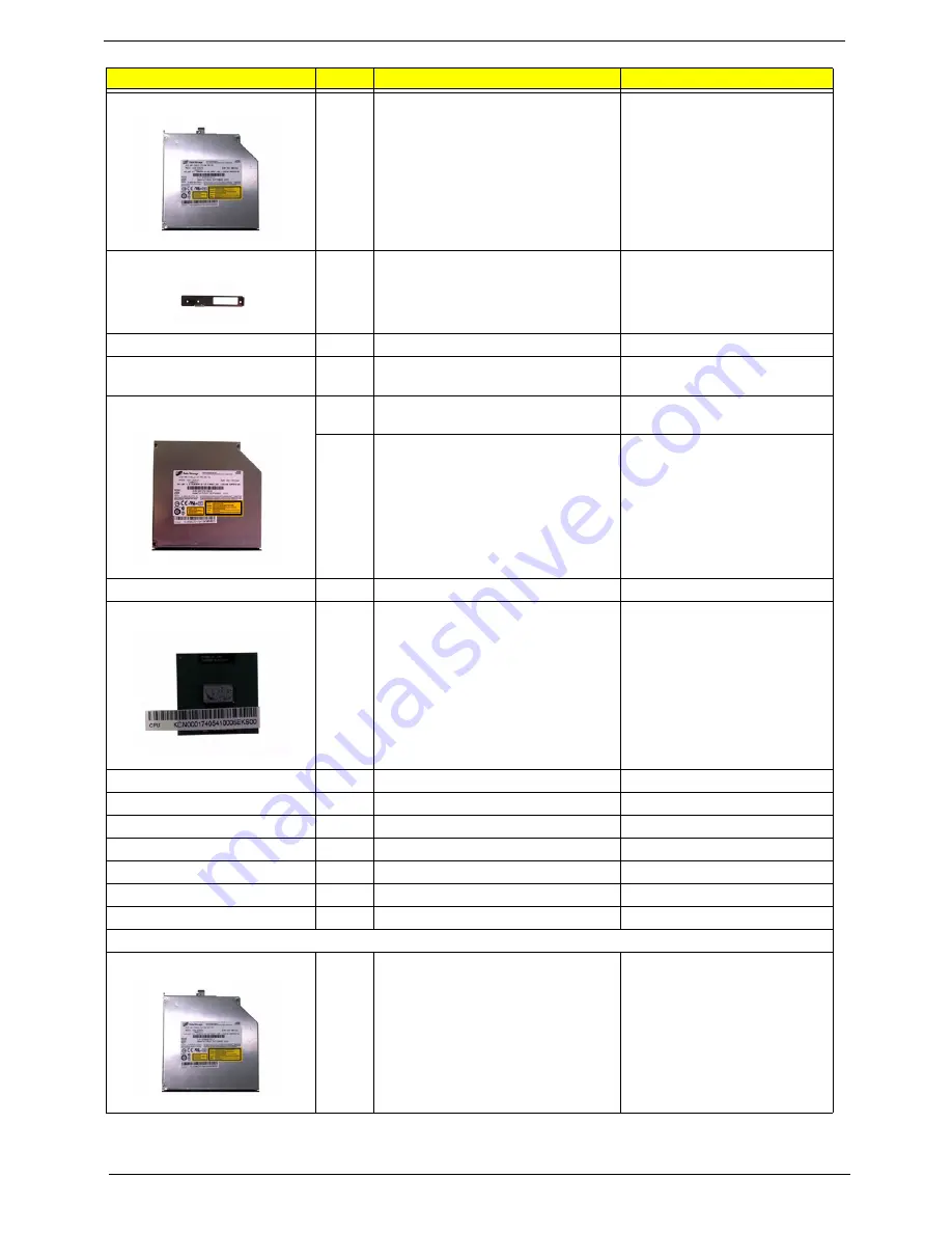
COMBO MODULE 24X 

6M.TB2V1.001

OPTICAL FIX HOLDER BRACKET

33.TB2V1.002

OPTICAL RAIL HOLDER

33.TB2V1.003

OPTICAL BEZEL GBASE FOR 
COMBO

42.TB2V1.003

COMBO MODULE 24X HLDS GCC-
4244N LF 1.00AB W/O BEZEL

KO.0240A.005

COMBO MODULE 24X LITEON 
SOSC-2485K W/O BEZEL

KO.02409.015

CPU/Processor

CPU CEL-M370 1.5GMHZ INTEL

KC.NV001.370

CPU DOTHAN730 1.6GMHZ INTEL

KC.N0001.730

CPU DOTHAN740 1.73GMHZ INTEL

KC.N0001.740

CPU DOTHAN725A 1.6GMHZ INTEL

KC.NA001.725

CPU CEL-M370 1.5G MHZ INTEL

KC.NC001.370

CPU CEL-M380 1.6GMHZ INTEL

KC.NV001.380

CPU CEL-M390 1.7GMHZ INTEL

KC.NV001.390

CPU CEL-M360 1.4GMHZ INTEL

KC.NV001.360

DVD Module

DVD-RW MODULE 8X

6M.TB2V1.002

Category

No.

Part Name and Description

Acer Part No.

Summary of Contents for Aspire 3050

Page 1: ...Aspire 5050 3050 Series Service Guide PRINTED IN TAIWAN Service guide files and updates are available on the ACER CSD web for more information please refer to http csd acer com tw...

Page 2: ...II Revision History Please refer to the table below for the updates made on Aspire 5050 3050 service guide Date Chapter Updates...

Page 3: ...ect to the contents hereof and specifically disclaims any warranties of merchantability or fitness for any particular purpose Any Acer Incorporated software described in this manual is sold or license...

Page 4: ...bits and pieces of additional information related to the current topic WARNING Alerts you to any damage that might result from doing or not doing specific actions CAUTION Gives precautionary measures...

Page 5: ...NOT be covered in this generic service guide In such cases please contact your regional offices or the responsible personnel channel to provide you with further technical details 2 Please note WHEN OR...

Page 6: ...VI...

Page 7: ...anagement for selected models 22 Acer eLock Management 24 Acer eRecovery Management 25 Acer eSettings Management 26 Acer ePerformance Management 26 Acer OrbiCam 27 Using the System Utilities 31 Acer G...

Page 8: ...ternal Diskette Drive Check 76 External CD ROM Drive Check 76 Keyboard or Auxiliary Input Device Check 76 Memory check 77 Power System Check 77 Touchpad Check 79 Power On Self Test POST Error Message...

Page 9: ...14 1 WXGA Acer CrystalBriteTM TFT LCD 1280 x 800 pixel resolution supporting simultaneous multi window viewing on dual displays via Acer GridVistaTM T 14 1 WXGA TFT LCD 1280 x 800 pixel resolution sup...

Page 10: ...T WLAN Acer InviLinkTM 802 11b g Wi Fi CERTIFIEDTM solution supporting Acer SignalUpTM wireless technology T WPAN Bluetooth 2 0 EDR Enhanced Data Rate T LAN Fast Ethernet Wake on LAN ready T Modem 56...

Page 11: ...ame Control Signal Power State Table 1 2V VCC_CORE 5VPCU 5VSUS 5V 3VPCU 3VS5 3VSUS 3V MAINON N A S5_ON SUSD MAIND 1 5V 1 8VS5 1 8VSUS 1 8V S0 S0 S5 S0 S3 S0 S0 S0 1 2V Sempron Rev F Single Core 465 Pi...

Page 12: ...N1 LCD Cable Connector 6 U9 ENE CB714 2 SW1 4 Quick Key Switch 7 SW5 10 Touchpad Switch 3 CN2 Touchpad Board Connector 8 U7 EC PC97551 4 U6 LAN RTL8100CL 9 CN3 Keyboard Connector 5 CN4 5 28 5 in 1 Car...

Page 13: ...ctor 4H 16 CN18 HDD Connector 4 CN10 So Dimm Connector 8H 17 CN20 MDC Connector 5 CN9 Power Board Connector 18 CN21 Internal MIC Connector 6 CN7 CRT Connector 19 CN22 Internal Speaker Connector 7 U16...

Page 14: ...see the bottom side of the main board 2 Find G1 jumper and short the jumper to clear BIOS password 11 U22 South Bridge SB460 24 PJ1 Battery Connector 12 CN19 PCMCIA Connector 25 SW11 Wireless Switch...

Page 15: ...unch buttons Buttons for launching frequently used program 4 Status indicators Light Emitting Diodes LEDs that light up to show the status of the computer s functions and components 5 Keyboard For ent...

Page 16: ...uetooth function Lights to indicate the status of Bluetooth communications optional 6 Wireless communication button indicator Press to enable disable Wireless function Lights to indicate the status of...

Page 17: ...levision or display device with S video input 4 USB 2 0 port Connects to USB 2 0 devices e g USB mouse USB camera 5 5 in 1 card reader Accepts Memory Stick MS Memory Stick PRO MS PRO MultiMediaCard MM...

Page 18: ...rom the drive location depends on model 4 Emergency eject hole Ejects the optical drive tray when the computer is turned off location depends on model 5 Modem RJ 11 port Connects to a phone line 6 DC...

Page 19: ...computer s main memory 2 Cooling fan Helps keep the computer cool Note Do not cover or obstruct the opening of the fan 3 Battery release latch Release the battery for removal 4 Battery bay Houses the...

Page 20: ...r Empowering Technology The mail and Web browser buttons are pre set to email and Internet programs but can be reset by users To set the Web browser mail and programmable buttons run the Acer Launch M...

Page 21: ...pad to perform selection and execution functions These two buttons are similar to the left and right buttons on a mouse Tapping on the Launch key Default application Acer Empowering Technology user pr...

Page 22: ...uchpad s responsiveness NOTE By default vertical and horizontal scrolling is enabled on your touchpad It can be disabled under Mouse settings in Windows Control Panel Function Left Button 1 Right Butt...

Page 23: ...l alphabetic characters typed are in uppercase Num lock Fn F11 When Num Lock is on the embedded keypad is in numeric mode The keys function as a calculator complete with the arithmetic operators and U...

Page 24: ...e used with other keys to provide a variety of function Tab Activates next taskbar button E Opens the My Computer window F1 Opens Help and Support F Opens the Find All Files dialog box R Opens the Run...

Page 25: ...monitor if connected and both Fn F6 Screen blank Turns the display screen backlight off to save power Press any key to return Fn F7 Touchpad toggle Turns the internal touchpad on and off Fn F8 Speaker...

Page 26: ...keyboard The US dollar sign 1 Open a text editor or word processor 2 Either directly press the Dollar key at the bottom right of the keyboard or hold Shift and then press the 4 key at the upper center...

Page 27: ...sword Before using Acer eLock Management and Acer eRecovery Management you must initalize the Empowering Technology password Right click on the Empowering Technology toolbard and select Password Setup...

Page 28: ...age referto the panel on the lower left hand side of the window For additional options click Settings to T Set alarms T Re load factory defaults T Select what actions will be taken when the cover is c...

Page 29: ...ement lets you project your computer s display to an external device or project using the hot key Fn F5 If auto detection hardware is implemented in the system your system display will be automaticall...

Page 30: ...crosoft Outlook The Acer eDataSecurity Management setup wizard will prompt you for a suvervisor password and default encryption This encryption will be used to encrypt files by default or you can choo...

Page 31: ...Chapter 1 23...

Page 32: ...lugged into the system T Optical drive deivces includes any kind of CD ROM or DVD ROM drives T Floppy disk drives 3 5 inch disks only T Interfaces includes serial ports parallel port infrared IR and B...

Page 33: ...set recovery point T Back up to CD DVD T Image data recovery tools T Recover from a hidden partition factory defaults T Recover from the HDD most recent user defined recovery point T Recover from CD D...

Page 34: ...Displays general system status and advanced monitoring for power users Acer ePerformance Management Acer ePerformance Management is a system optimization tool that boosts the performance of your Acer...

Page 35: ...225 degree ergonomic rotation allows you to capture high resolution photos or videos up front or at the back of the LCD panel The Acer OrbiCam fully supports the Acer Video Conference technology so th...

Page 36: ...r face in front or at the back of the LCD panel NOTE Do not rotate the camera clockwise to prevent damage to the device Launching the Acer OrbiCam To launch the Acer OrbiCam double click on the Acer O...

Page 37: ...for captured photos or videos Camera Settings T Basic settings Click the Camera Settings icon on the bottom right corner of the capture display then select Camera Settings from the pop up menu You ca...

Page 38: ...red angle then click the Take a Picture or Record a Video button The Windows Picture and Fax Viewer or the Windows Media Player automatically launches to display or play a preview of the photo video c...

Page 39: ...ess this function please go to Start All Programs and click on Acer GridVista You may choose any one of the four display settings indicated below Double verticle Triple primary at left Triple primary...

Page 40: ...ger Launch Manager allows you to set the four easy launch buttons located above the keyboard You can access the Launch Manager by clicking on Start All Programs Launch Manager to start the application...

Page 41: ...Table DTS degree C Fan Speed rpm Acoustic Level dBA 45 50 0 3300 29 55 63 0 3800 33 65 70 3800 4100 38 75 80 4100 4400 40 86 88 4400 5300 40 BIOS Item Specification BIOS vendor Phneoix BIOS Version 1...

Page 42: ...rol Always enabled Cache scheme control Fixed in write back System Memory Item Specification Memory controller Built in AMD Turion 64 dual core or Sempron singel core processor Memory size 0MB no on b...

Page 43: ...4MB 1536MB 512MB 2048MB 2560MB 1024MB 0MB 1024MB 1024MB 256MB 1280MB 1024MB 512MB 1536MB 1024MB 1024MB 2048MB 1024MB 2048MB 3072MB 2048MB 0MB 2048MB 2048MB 256MB 2304MB 2048MB 512MB 2560MB 2048MB 1024...

Page 44: ...endor Model Name HGST HTS421240H9 A WD WD600UE 22HCT0 HGST HTS541060G9 A SEAGATE ST98823A HGST MORAGA HTS541010G9 A Seagate ST9100824A HGST HTS541612J9 AT WD1200UE 22KVT0 ML60 Capacity MB 40000 60000...

Page 45: ...ndard CD DA 4 Reads and writes CD R discs conforming to Orange Book Part 2 5 Reads and writes CD RW discs conforming to Orange Book Part 3 6 Reads data in DVD ROM For Philips SB5265 Applicable DVD for...

Page 46: ...Extra CD CD text DVD DVD VIDEO DVD ROM DVD R 3 9GB 4 7GB DVD R DL DVD RW DVD RAM DVD R DVD R DL DVD RW For Toshiba TSST TS L632D CD CD DA Red Book Standard Audio CD CD TEXT CD ROM Yellow Book Mode1 2...

Page 47: ...uantity Yes 2 1 5W speakers Video Interface Item Specification Chipset Built in ATI RS485 Package Micro FCBGA 465 pin Interface internal PCIE Supports ZV Zoomed Video port Yes Video Memory Item Specif...

Page 48: ...lt in ATI SB460 PCMCIA 5 in 1 Card Reader ENE CB714 1410 Audio Codec Realtek ALC883 Keyboard Item Specification Keyboard controller NS PC97541V Total number of keypads 88 89 key Windows logo key Yes I...

Page 49: ...e Display Mode Normally White Normally White Normally White Typical White Luminance cd m2 also called Brightness 185 185 200 Luminance Uniformity N A N A N A Contrast Ratio 300 500 400 Response Time O...

Page 50: ...iency 82 min 115VAC input full load System Power Management ACPI mode Power Management Mech Off G3 All devices in the system are turned off completely Soft Off G2 S5 OS initiated shutdown All devices...

Page 51: ...ou want to change boot device without entering BIOS Setup Utility please set the parameter to enabled Press F12 during POST to enter multi boot menu In this menu user can change boot device without en...

Page 52: ...em T Press while you are in any of the menu options to go to the Exit menu T In any menu you can load default settings by pressing t You can also press u to save any changes made and exit the BIOS Set...

Page 53: ...field displays the VGA firmware version of the system KBC Ver This field shows the keyboard Serial Number This field displays the serial number of this unit Asset Tag Number This field displays the as...

Page 54: ...46 Chapter 2 UUID Number This will be visible only when an internal LAN device is presenting UUID 32bytes Parameter Description...

Page 55: ...Utility Information Main Security Boot Exit Item Specific Help System Time 15 27 09 System Date 10 11 2006 System Memory 633 KB Extended Memory Video Memory 766 MB 256MB Quiet Boot Enabled Power on d...

Page 56: ...s if Customer Logo will be displayed or not shows Summary Screen is disabled or enabled Enabled Customer Logo is displayed and Summary Screen is disabled Disabled Customer Logo is not displayed and Su...

Page 57: ...ion Main Boot Item Specific Help Supervisor Password Is Clear User Password Is HDD 0 Password Clear Clear Set Supervisor Password Set User Password Set HDD 0 Password Password on Boot Disabled Supervi...

Page 58: ...Set 4 If desired you can opt to enable the Password on boot parameter 5 When you are done press u to save the changes and exit the BIOS Setup Utility Parameter Description Option User Password is Show...

Page 59: ...BIOS Setup Utility Changing a Password 1 Use the w and y keys to highlight the Set Supervisor Password parameter and press the e key The Set Password box appears 2 Type the current password in the En...

Page 60: ...urrent password entered does not match the actual current password the screen will show you the Setup Warning If the new password and confirm new password strings do not match the screen will display...

Page 61: ...igure device Use Up and Down arrows to select a device and moves the device up or down f and r specifies the device fixed or removable x exclude or include the device to boot Shift 1 enables or disabl...

Page 62: ...data to CMOS Load Setup Default Load default values for all SETUP item Discard Changes Load previous values from CMOS for all SETUP items Save Changes Save Setup Data to CMOS PhoenixBIOS Setup Utility...

Page 63: ...ry Diskette before you use the Phlash utility NOTE Do not install memory related drivers XMS EMS DPMI when you use the Phlash NOTE Please use the AC adaptor power supply when you run the Phlash utilit...

Page 64: ...key in wrong HDD password for three time HDD password error code would display on the screen See the image below T If you need to solve HDD password locked problem you can run HDD_PW EXE 1 Key in hdd...

Page 65: ...Chapter 2 57 Remove BIOS Password T If you key in wrong Supervisor Password for three time System Disabled would display on the screen See the image below...

Page 66: ...er 2 T If you need to solve BIOS password locked problem you can run BIOS_PW EXE 1 Key in bios_pw 14452 0 2 Choose one upper case string T Reboot the system and key in qjjg9vy or 07yqmjd to BIOS user...

Page 67: ...Chapter 2 59...

Page 68: ...60 Chapter 2...

Page 69: ...preventing electrostatic discharge T Small Philips screw driver T Philips screwdriver T Plastic flat head screw driver T Tweezers NOTE The screws for the different components vary in size During the...

Page 70: ...Begin Before proceeding with the disassembly procedure make sure that you do the following 1 Turn off the power to the system and all peripherals 2 Unplug the AC adapter and all power and signal cable...

Page 71: ...Battery Middle Cover HDD Cover DIMM Cover H 2 P 1 HDD Module O 4 H 3 CPU Lower Case Assembly 86 9A353 3R0 2 Modem Board Memory ODD Module Wireless LAN Card HDD HDD Bracket M 4 Keyboard LCD Module J 2...

Page 72: ...G SCREW M2 3 NYLON 1JMCPC 420325 86 9A352 3R0 H SCREW 86 9A352 4R0 I SCREW M2 5 4L NYLOCK BLACK ZN 86 9A353 4R0 J SCREW M2 5X6 86 9A353 6R0 K SRW M2 5 8L B ZN NYLOK 700 86 9A353 8R0 L SCRW M2 5 L3 NON...

Page 73: ...Chapter 3 65 Removing the Battery Pack 1 Unlock the battery lock 2 Slide the battery latch then remove the battery...

Page 74: ...rew holding the HDD module as shown 4 Then disconnect the entire HDD module from the main unit Removing the Memory the Wireless LAN Card the Modem Board 1 Remove the two screws fastening the RAM cover...

Page 75: ...ard then disconnect the modem board cable Removing the ODD Module 1 Remove one screw holding the ODD module on the bottom side 2 Push the ODD module outwards then remove it Removing the LCD Module inc...

Page 76: ...eless LAN antenna set from the guide line as shown 7 Disconnect the LCD cable from the main board 8 Disconnect the lid switch cable from the main board 9 If you laptop has CCD module web camera module...

Page 77: ...y on the bottom 3 Detach the upper case assembly from the lower case assembly Disassembling the Upper Case Assembly 1 Remove the two screws fastening the media board 2 Use a tweezers or a flat headed...

Page 78: ...Carefully detach the main board from the lower case as shown 7 Remove the two screws holding the daughter board to the main board 8 Then detach the daughter board from the main board 9 Disconnect the...

Page 79: ...Chapter 3 71...

Page 80: ...sconnect the LVDS cable as shwon 5 Disconnect the inverter cable then take out the inverter 6 Remove five screws holding the LCD assembly to the LCD cover 7 Take out the LCD assembly from the LCD cove...

Page 81: ...Chapter 3 73 13 Then remove the left LCD bracket from the LCD 14 Tear off the mylar fastening the LCD cable 15 Disconnect the LCD cable from the LCD...

Page 82: ...1 Remove two screws holding the HDD bracket 2 Then remove two screws fastening the HDD braket on the other side 3 Remove the HDD bracket Disassembling the ODD Module 1 Remove the two screws holding th...

Page 83: ...which page to go to Symptoms Verified Go To Power failure The power indicator does not go on or stay on Power System Check on page 77 POST does not complete No beep or error codes are indicated Power...

Page 84: ...o it The label can cause damage to the drive or can cause the drive to fail Do the following to select the test device 1 Boot from the diagnostics diskette and start the diagnostics program 2 See if C...

Page 85: ...nstructions in the message window NOTE Make sure that the DIMM is fully installed into the connector A loose connection can cause an error Power System Check To verify the symptom of the problem power...

Page 86: ...following T Replace the System board T If the problem is not corrected see Undetermined Problems on page 94 T If the voltage is not correct go to the next step NOTE An audible noise from the power ad...

Page 87: ...attery pack that has less than 50 of the total power remaining when installed in the computer If the battery status indicator does not light up remove the battery pack and let it return to room temper...

Page 88: ...xt possible FRU to be replaced when servicing a computer If the symptom is not listed see Undetermined Problems on page 94 The following lists the error messages that the BIOS displays on the screen a...

Page 89: ...Fixed Disk Reconnect hard disk drive connector Load Default Settings in BIOS Setup Utility Hard disk drive System board Stuck Key see Keyboard or Auxiliary Input Device Check on page 76 Keyboard error...

Page 90: ...e drive is defined with the proper diskette type in BIOS Setup Utility System cache error Cache disabled System board CPU ID System board DMA Test Failed DIMM System board Software NMI Failed DIMM Sys...

Page 91: ...ource battery pack and power adapter See Power System Check on page 77 Reconnect the LCD connector Hard disk drive LCD inverter ID LCD cable LCD Inverter LCD System board No beep power on indicator tu...

Page 92: ...alize keyboard controller 16h 1 2 2 3 BIOS ROM checksum 17h Initialize cache before memory autosize 18h 8254 timer initialization 1Ah 8237 DMA controller initialization 1Ch Reset Programmable Interrup...

Page 93: ...play service 5Ah Display prompt Press F2 to enter SETUP 5Bh Disable CPU cache 5Ch Test RAM between 512 and 640 KB 60h Test extended memory 62h Test extended memory address lines 64h Jump to User Patch...

Page 94: ...ump to UserPatch2 93h Build MPTABLE for multi processor boards 95h Install CD ROM for boot 96h Clear huge ES segment register 97h Fixup Multi Processor table 98h 1 2 Search for option ROMs One long tw...

Page 95: ...Force check optional C9h Extended checksum optional D2h Unknown interrupt Code Beeps E0h Initialize the chipset E1h Initialize the bridge E2h Initialize the CPU E3h Initialize the system timer E4h Ini...

Page 96: ...88 Chapter 4 F5h Boot to Mini DOS F6h Clear Huge Segment F7h Boot to Full DOS Code Beeps...

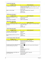
Page 97: ...er ID LCD cable LCD inverter LCD System board LCD has extra horizontal or vertical lines displayed LCD inverter ID LCD inverter LCD cable LCD System board Indicator Related Symptoms Symptom Error Acti...

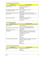
Page 98: ...ystem DIMM System board Speaker Related Symptoms Symptom Error Action in Sequence In Windows multimedia programs no sound comes from the computer Audio driver Speaker System board Internal speakers ma...

Page 99: ...devices Enter BIOS Setup Utility to execute Load Default Settings then reboot system Reconnect hard disk CD ROM diskette drives External display does not work correctly Press Fn F5 LCD CRT Both displ...

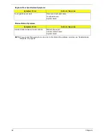
Page 100: ...ed Problems on page 94 Touchpad does not work Reconnect touchpad cable Touchpad board System board Modem Related Symptoms Symptom Error Action in Sequence Internal modem does not work correctly Modem...

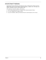
Page 101: ...discharge or software errors FRU replacement should be considered only when a recurring problem exists When analyzing an intermittent problem do the following 1 Run the advanced diagnostic test for th...

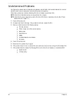
Page 102: ...perating correctly See Power System Check on page 77 1 Power off the computer 2 Visually check them for damage If any problems are found replace the FRU 3 Remove or disconnect all of the following dev...

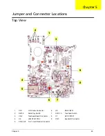
Page 103: ...9 ENE CB714 2 SW1 4 Quick Key Switch 7 SW5 10 Touchpad Switch 3 CN2 Touchpad Board Connector 8 U7 EC PC97551 4 U6 LAN RTL8100CL 9 CN3 Keyboard Connector 5 CN4 5 28 5 in 1 Card Reader Connector 2 1 3 4...

Page 104: ...ctor 4H 16 CN18 HDD Connector 4 CN10 So Dimm Connector 8H 17 CN20 MDC Connector 5 CN9 Power Board Connector 18 CN21 Internal MIC Connector 6 CN7 CRT Connector 19 CN22 Internal Speaker Connector 7 U16...

Page 105: ...see the bottom side of the main board 2 Find G1 jumper and short the jumper to clear BIOS password 11 U22 South Bridge SB460 24 PJ1 Battery Connector 12 CN19 PCMCIA Connector 25 SW11 Wireless Switch...

Page 106: ...98 Chapter 5...

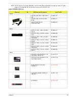
Page 107: ...is made it will not be noted on the printed Service Guide For ACER AUTHORIZED SERVICE PROVIDERS your Acer office may have a DIFFERENT part number code from those given in the FRU list of this printed...

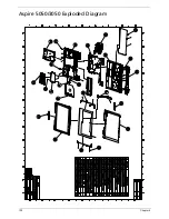
Page 108: ...100 Chapter 6 Aspire 5050 3050 Exploded Diagram...

Page 109: ...A54LF AP 06506 003 Battery BATTERY PACK LI 6CELL 2 0MAH SANYO BT 00603 014 BATTERY PACK LI 6CELL 2 0MAH SONY BT 00604 006 BATTERY PACK LI 6CELL 2 0MAH PANASONIC BT 00605 002 BATTERY PACK LI 6CELL 2 4M...

Page 110: ...ORD 10A 125V US 27 T30V1 001 POWER CORD 7A 250V 2PIN KOREAN 27 01518 531 POWER CORD 3A 250V 3PIN UK 27 01518 541 POWER CORD 220V 3PIN EUR 27 T30V1 004 POWER CORD 7A 125V 2PIN JAPEN 27 01518 551 POWER...

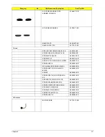
Page 111: ...W MICROPHONE TRAVELMATE 60 TCZV1 003 MIDDLE COVER W MICROPHONE ASPIRE 60 ADKV1 003 FRONT COVER 42 TCZV1 003 DIMM COVER 42 TCZV1 002 HDD COVER 42 TCZV1 001 TOUCHPAD BRACKET 33 TCZV1 001 UPPER CASE TRA...

Page 112: ...5K W O BEZEL KO 02409 015 CPU Processor CPU CEL M370 1 5GMHZ INTEL KC NV001 370 CPU DOTHAN730 1 6GMHZ INTEL KC N0001 730 CPU DOTHAN740 1 73GMHZ INTEL KC N0001 740 CPU DOTHAN725A 1 6GMHZ INTEL KC NA001...

Page 113: ...AG1 NOBZL LF KU 00807 022 DUAL HLD GWA 4082N MORAR GCP03 KU 0080D 019 S MUTI PAN UJ 850 AG1 NOBZL LF KU 00807 025 Fan FAN SUNON AG1 23 TB2V1 003 HDD Hard Disk Drive HDD MODULE 40G TBD ASSY HDD BRACKET...

Page 114: ...AT00 KH 08007 012 HDD 80G WD WD800UE 22HCT0 KH 08008 027 HDD MODULE 100G TBD HDD BRACKET 33 TB2V1 004 HDD 100GB SEAGATE ST9100825A KH 10001 003 HDD 100G TOSHIBA MK1031GAS KH 10004 001 HDD 100G HITACHI...

Page 115: ...G KB A2707 017 KEYBOARD 88KEY DARFON NSK H3M0R RUSSIAN KB A2707 025 KEYBOARD 89KEY DARFON NSK H3M0S SP KB A2707 003 KEYBOARD 89KEY DARFON NSK H3M0T TURKISH KB A2707 020 KEYBOARD 89KEY DARFON NSK H3M0U...

Page 116: ...SP KB T5007 003 KEYBOARD 89KEY DARFON NSK AEK0T TURKISH KB T5007 020 KEYBOARD 89KEY DARFON NSK AEK0U UK KB T5007 007 KEYBOARD 89KEY DARFON NSK AEK0W SWEDEN KB T5007 015 KEYBOARD 89KEY DARFON NSK AEK1...

Page 117: ...005 HINGE PACK LEFT RIGHT 6K TB2V1 001 LCD 14 1 WXGA AU B141EW01 V 1 NONE GLARE LK 14105 013 LCD 14 WXGA SAMSUNG LTN141W1 L01 NONE GLARE LK 14106 004 LCD 14 1 WXGA LG LP141WX1 TL02 NONE GLARE LK 14108...

Page 118: ...SLOT RTC BATTERY MB TCZV1 001 Battery RTC BATTERY 23 TCZV1 004 PCMCIA Slot PC Card Slot PCMCIA SLOY 22 TB2V1 001 Memory SDIMM 256M INFINEON HYS64T32000HDL 3 7 A KN 25602 023 DIMM 256M NANYA NT256T64U...

Page 119: ...HEAD 86 5A353 120 SCREW M2 5 6 86 9A323 6R0 WCH MSN CBZ SCREW M2X2 5 86 9A352 2R5 SCREW M2 3 NYLON 1JMCPC 420325 86 9A352 3R0 SCREW 86 9A352 4R0 SCREW M2 5 4L NYLOCK BLACK ZN 86 9A353 4R0 SRW M2 5 8L...

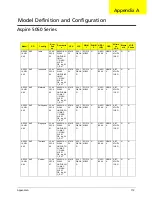
Page 120: ...WXGA G SO512 MBII5 N N80G B5 4K NSM8 X ABT_ ATH54 13BG N N AS505 1ANW XMi AAP Philippines LX AV 30C 0 04 AS5051AN WXMi LINPUSPH 1 UMAC 1 512 80 6L 5R CB_bg_0 3 C_AN ATMK 36 N14 1 WXGA G SO512 MBII5 N...

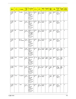
Page 121: ...AWX Mi PA ACLA Spanish LX AV 305 01 0 AS5051AW XMi XPHES1 UMAC 1 512 120 6L 5R CB_bg_0 3 C_AN ATMK 36 N14 1 WXGA G SO512 MBII5 N N120 GB5 4 K NSM8 X ABT_ ATH54 13BG N N AS505 1AWX Mi PA USA Canada LX...

Page 122: ...C 2 512 120 BT 6L 5R CB_bg_0 3 C_AN ATMK 36 N14 1 WXGA G SO512 MBII6 SO512 MBII6 N120 GB5 4 K NSM8 X ABT_ ATH54 13BG FOX_ BRM_ 2 0 N AS505 2WXM i TWN GCTWN S2 AV 305 00 2 AS5052WX Mi XPHTC1 UMAC 2 512...

Page 123: ...X Mi AAP Singapore LX AV 30J 01 2 AS5051AW XMi MCESG1 UMAC 1 1G 120 6L 5R CB_bg_0 3 C_AN ATMK 36 N14 1 WXGA G SO1G BII6 N N120 GB5 4 K NSM8 X ABT_ ATH54 13BG N N AS505 1AWX Mi AAP India LX AV 30J 01 3...

Page 124: ...dia LX AV 30J 00 5 AS5052WX Mi MCEIL1 UMAC 1 1G 120 6L 5R CB_bg_0 3 C_AN ATTL5 0 N14 1 WXGA G SO1G BII6 N N120 GB5 4 K NSM8 X ABT_ ATH54 13BG N N AS505 2WXM i AAP Indonesia LX AV 30J 00 6 AS5052WX Mi...

Page 125: ...WXMi LINPUSVN 1 UMAC 1 512 60 6L 5R CB_bg_0 3 C_AN ATMK 36 N14 1 WXGA G SO512 MBII5 N N60G B5 4K NSM8 X ABT_ ATH54 13BG N N AS505 1ANW XMi AAP Thailand LX AV 30C 0 16 AS5051AN WXMi LINPUSTH 2 UMAC 1 5...

Page 126: ...2 AS5051AW XMi MCEBE6 UMAC 2 512 100 6L 5R_bg_0 3 C_AN ATMK 36 N14 1 WXGA SO512 MBII6 SO512 MBII6 N100 GB5 4 K NSM8 X ABT_ BRM4 318BG N N AS505 1AWX Mi EMEA Middle East LX AV 30J 04 3 AS5051AW XMi MC...

Page 127: ...2 8 AS5051AW XMi MCEDEB UMAC 2 512 100 6L 5R_bg_0 3 C_AN ATMK 36 N14 1 WXGA SO512 MBII6 SO512 MBII6 N100 GB5 4 K NSM8 X ABT_ BRM4 318BG N N AS505 1AWX Mi EMEA Holland LX AV 30J 03 3 AS5051AW XMi MCENL...

Page 128: ...X AV 30J 04 5 AS5051AW XMi MCESW8 UMAC 2 512 100 6L 5R_bg_0 3 C_AN ATMK 36 N14 1 WXGA SO512 MBII6 SO512 MBII6 N100 GB5 4 K NSM8 X ABT_ BRM4 318BG N N AS505 1AWX Mi EMEA UK LX AV 30J 04 6 AS5051AW XMi...

Page 129: ...AV 305 02 3 AS5051AW XMi XPHDE7 UMAC 2 512 100 6L 5R_bg_0 3 C_AN ATMK 36 N14 1 WXGA SO512 MBII6 SO512 MBII6 N100 GB5 4 K NSM8 X ABT_ BRM4 318BG N N AS505 1AWX Mi EMEA Greece LX AV 305 03 3 AS5051AW X...

Page 130: ...3 0 AS5051AW XMi XPHSLO2 UMAC 2 512 100 6L 5R_bg_0 3 C_AN ATMK 36 N14 1 WXGA SO512 MBII6 SO512 MBII6 N100 GB5 4 K NSM8 X ABT_ BRM4 318BG N N AS505 1AWX Mi EMEA Eastern Europe LX AV 305 02 9 AS5051AW X...

Page 131: ...S5051AW XMi XPHWFRB 1W UMAC 2 512 100 6L 5R_bg_0 3 C_AN ATMK 36 N14 1 WXGA SO512 MBII6 SO512 MBII6 N100 GB5 4 K NSM8 X ABT_ BRM4 318BG N N AS505 1AWX Mi EMEA Italy LX AV 305 03 7 AS5051AW XMi XPHWIT21...

Page 132: ...2 UMAC 1 512 80 6L 5R CB_bg_0 3 C_AN ATMK 36 N14 1 WXGA G SO512 MBII5 N N80G B5 4K NCB2 4X ABT_ BRM4 318BG N N AS505 1ANW XCi AAP Malaysia LX AV 30C 0 18 AS5051AN WXCi LINPUSMA 2 UMAC 1 512 80 6L 5R C...

Page 133: ...05 3 AS5051AW XMi MCESI1 UMAC 1 512 100 BT 6L 5R_bg_VP _0 3C_AN ATMK 36 N14 1 WXGA SO512 MBII6 N N100 GB5 4 K NSM8 X ABT_ BRM4 318BG FOX_ BRM_ 2 0 BT VoIP PCMC IA AS505 2NWX Mi AAP Thailand LX AV 30C...

Page 134: ...12 100 BT 6L 5R_bg_VP _0 3C_AN ATMK 36 N14 1 WXGA SO512 MBII6 N N100 GB5 4 K NSM8 X ABT_ BRM4 318BG FOX_ BRM_ 2 0 BT VoIP PCMC IA AS505 1AWX Mi EMEA Russia LX AV 305 04 5 AS5051AW XMi XPHRU1 UMAC 1 51...

Page 135: ...AS5051AW XMi MCEDEB UMAC 2 512 120 6L 5R_bg_0 3 C_AN ATMK 36 N14 1 WXGA SO512 MBII5 SO512 MBII5 N120 GB5 4 K NSM8 X ABT_ BRM4 318BG N N AS505 1AWX Mi EMEA Middle East LX AV 30J 07 0 AS5051AW XMi MCEAR...

Page 136: ...3 AS5051AW XMi MCENO5 UMAC 1 512 80 6L 5R_bg_0 3 C_AN ATMK 36 N14 1 WXGA SO512 MBII6 N N80G B5 4K NSM8 X ABT_ BRM4 318BG N N AS505 1AWX Mi EMEA Norway LX AV 30J 07 5 AS5051AW XMi MCENO5 UMAC 2 512 12...

Page 137: ...07 2 AS5051AW XMi MCETR5 UMAC 2 512 120 6L 5R_bg_0 3 C_AN ATMK 36 N14 1 WXGA SO512 MBII5 SO512 MBII5 N120 GB5 4 K NSM8 X ABT_ BRM4 318BG N N AS505 1AWX Mi EMEA Italy LX AV 30J 07 6 AS5051AW XMi MCEWIT...

Page 138: ...05 05 2 AS5051AW XMi XPHCS2 UMAC 2 512 120 6L 5R_bg_0 3 C_AN ATMK 36 N14 1 WXGA SO512 MBII5 SO512 MBII5 N120 GB5 4 K NSM8 X ABT_ BRM4 318BG N N AS505 1AWX Mi EMEA UK LX AV 30J 08 3 AS5051AW XMi MCEWUK...

Page 139: ...5 05 3 AS5051AW XMi XPHPL6 UMAC 2 512 120 6L 5R_bg_0 3 C_AN ATMK 36 N14 1 WXGA SO512 MBII5 SO512 MBII5 N120 GB5 4 K NSM8 X ABT_ BRM4 318BG N N AS505 1AWX Mi EMEA Holland LX AV 305 06 7 AS5051AW XMi XP...

Page 140: ...zerland LX AV 305 06 4 AS5051AW XMi XPHSW5 UMAC 2 512 120 6L 5R_bg_0 3 C_AN ATMK 36 N14 1 WXGA SO512 MBII5 SO512 MBII5 N120 GB5 4 K NSM8 X ABT_ BRM4 318BG N N AS505 1AWX Mi EMEA UK LX AV 305 06 5 AS50...

Page 141: ...052N WXMi LINPUSIL1 UMAC 1 512 80 BT 6L 5R CB_bg_0 3 C_AN ATTL5 0 N14 1 WXGA G SO512 MBII5 N N80G B5 4K NSM8 X ABT_ ATH54 13BG FOX_ BRM_ 2 0 N Model RO Country Acer Part no Descriptio n CPU LCD DIMM 1...

Page 142: ...G N AS305 3NWX Mi AAP India LX AV 20C 0 02 AS3053N WXMi LINPUSIL1 UMAC 1 512 60 6L 5R CB_bg_0 3 C_AN SMP64342 5W N14 1W XGAG SO512 MBII5 N N60GB5 4K NSM8 X ABT_BR M4318B G N AS305 3NWX Mi AAP Singap o...

Page 143: ...PA USA Canad a LX AV 205 00 9 AS3053WX Mi XPHFR1 UMAC 1 512 80 6L 5R CB_bg_0 3 C_AN SMP64342 5W N14 1W XGAG SO512 MBII5 N N80GB5 4K NSM8 X ABT_BR M4318B G N AS305 3WXM i PA ACLA Spanis h LX AV 205 01...

Page 144: ...AS3053WX Mi XPHWSG2 1W UMAC 1 512 60 6L 5R CB_bg_0 3 C_AN SMP64342 5W N14 1W XGAG SO512 MBII5 N N60GB5 4K NSM8 X ABT_BR M4318B G N AS305 3WXM i PA ACLA Portug uese LX AV 205 01 1 AS3053WX Mi XPHXC1 UM...

Page 145: ...PA ACLA Spanis h LX AV 20J 00 7 AS3053WX Mi MCEES1 UMAC 1 512 60 6L 5R CB_bg_0 3 C_AN SMP64342 5W N14 1W XGAG SO512 MBII5 N N60GB5 4K NSM8 X ABT_BR M4318B G N AS305 3WXM i PA USA Canad a LX AV 206 00...

Page 146: ...key LX AV 20C 0 10 AS3053N WXMi LINPUSTR 1 UMAC 1 512 60 6L 5R_bg_0 3 C_AN SMP64342 5W N14 1W XGA SO512 MBII5 N N60GB5 4K NSM8 X ABT_BR M4318B G N AS305 3WXM i EMEA Turkey LX AV 205 01 6 AS3053WX Mi X...

Page 147: ...XP Home Windows XP Pro environment Refer to the following lists for components adapter cards and peripherals which have passed these tests Regarding configuration combination and test procedures plea...

Page 148: ...orer 4 0 USB and PS 2 Compatible Optical QSMC Microsoft Optical Mouse Blue USB and PS 2 Compatible Logitech Cordless TrackMan Fx Trackball Optical Microsoft Wireless Optical Mouse Blue USB PS 2 Micros...

Page 149: ...ard 1394 CardBus Card Gppdvion PCMCIA convert to 1394 CardBus 2 Ports USB2 0 CardBus Card IOGEAR USB 2 0 2 Port CardBus Card INTOPIC USB 2 0 4 Port Notebook Card CardBus QSMC Wireless Lan Card 3COM 11...

Page 150: ...lorer 4 0 USB and PS 2 Compatible Optical QSMC Microsoft Optical Mouse Blue USB and PS 2 Compatible Logitech Cordless TrackMan Fx Trackball Optical Microsoft Wireless Optical Mouse Blue USB PS 2 Micro...

Page 151: ...ard 1394 CardBus Card Gppdvion PCMCIA convert to 1394 CardBus 2 Ports USB2 0 CardBus Card IOGEAR USB 2 0 2 Port CardBus Card INTOPIC USB 2 0 4 Port Notebook Card CardBus QSMC Wireless Lan Card 3COM 11...

Page 152: ...144 Appendix B...

Page 153: ...sktop and Server models including T Service guides for all models T User s manuals T Training materials T Bios updates T Software utilities T Spare parts lists T TABs Technical Announcement Bulletin F...

Page 154: ...146 Appendix C...

Page 155: ...ymptom to Spare Part Index 80 External CD ROM Drive Check 76 F Features 1 Flash Utility 55 Floppy Disk removing the 72 FRU Field Replaceable Unit List 99 H Hard disk 36 HDD 36 Hot Keys 15 I Indicators...

Page 156: ...ystem Memory 34 System Utilities 43 T Test Compatible Components 139 Top 95 Touchpad Check 79 Troubleshooting 75 U Undetermined Problems 94 USB 39 utility BIOS 43 V Video 39 W Windows XP Environment T...

Page 157: ...Index 149...
Reviews: