Troubleshooting
4-3
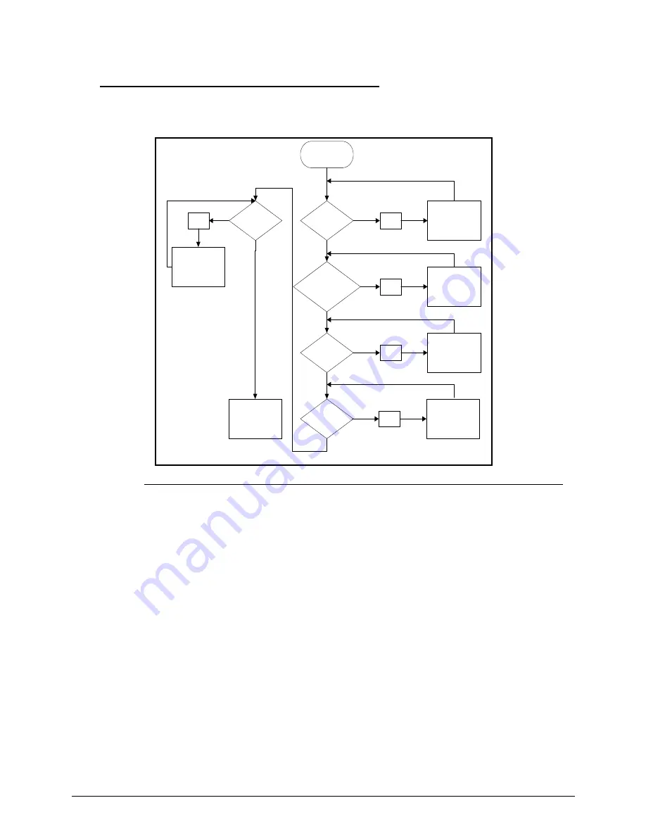
No Display Issues
0
If the Display does not work, perform the following, one at a time. Do not replace a non-defective FRU:
Figure 4-2.
No Display Issue
No POST or Video
0
If the POST or video does not appear, perform the following, one at a time.
1.
Make sure that internal display is selected. Switching between internal and external by
pressing
Fn+F5
. Reference Product pages for specific model procedures.
2.
Make sure the computer has power by checking for one of the following:
Fans start up
Status LEDs illuminate
If no power, refer to
Power On Issues
.
3.
Drain stored power by removing the power cable and battery. Hold the power button for 10
seconds.
4.
Connect the power and reboot the computer.
5.
Connect an external monitor to the computer and switch between the internal display and
the external display is by pressing
Fn+F5
.
6.
If the POST or video appears on the external display only, refer to
LCD Failure
.
7.
Disconnect power and all external devices including port replicators or docking stations.
Remove any memory cards and CD/DVD discs.
START
Power On?
Ext.DDRRAM
Module well
connected?
Ext DDRRAM
Module OK?
CPU Thermal
Module well
screwed?
LCD Moduel
OK?
NG
Power On Issue
Replace MB
NG
Check Connection
NG
Replace
Ext. DDRRAM
Module
NG
Fasten Screw
NG
Replace LCD
Panel/LCD Cable
Summary of Contents for Aspire 3750
Page 1: ...Acer AS3750 AS3750G SERVICEGUIDE ...
Page 4: ...iv ...
Page 40: ...1 36 Hardware Specifications and Configurations ...
Page 57: ...System Utilities 2 17 Figure 2 19 Unlock Password ...
Page 75: ...3 15 Figure 3 24 Memory Module Figure 3 25 Memory Module ...
Page 79: ...3 19 ...
Page 83: ...3 23 Top case disassembly M2 5 3 5L 3 Table 3 1 Step Screw Quantity Screw Type ...
Page 87: ...3 27 2 Disconnect the RTC BATTERY cable then take the battery away Figure 3 45 RTC BATTERY ...
Page 94: ...3 34 Figure 3 58 LCD Module ...
Page 98: ...3 38 Figure 3 65 LCD Panel ...
Page 101: ...3 41 Figure 3 70 Hinge ...
Page 103: ...3 43 Figure 3 73 CPU Module Figure 3 74 CPU Module ...
Page 105: ...3 45 Figure 3 77 Main board Figure 3 78 Main board ...
Page 108: ...3 48 Figure 3 83 Blue tooth Module Figure 3 84 Blue tooth Module ...
Page 112: ...3 52 Figure 3 91 Top case Figure 3 92 Top case ...
Page 115: ...3 55 Figure 3 97 Memory Figure 3 98 Memory ...
Page 163: ...FRU Field Replaceable Unit List 6 9 ...
Page 192: ...6 38 FRU Field Replaceable Unit List ...
Page 268: ...7 76 Model Definition and Configuration ...
Page 272: ...8 4 Test Compatible Components ...


