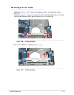
Machine Maintenance
3-19
Main Unit Disassembly Process
0
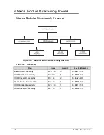
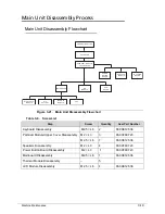
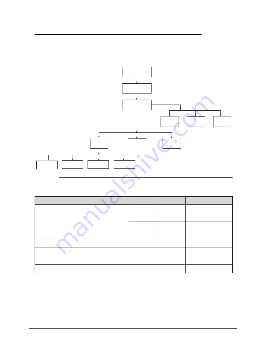
Main Unit Disassembly Flowchart
0
Figure 3-21. Main Unit Disassembly Flowchart
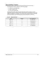
Table 3-9. Screw List
Step
Screw
Quantity
Acer Part Number
Keyboard Disassembly
M2.5 × L6
2
86.00E12.536
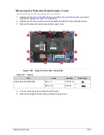
Palmrest Module/Upper Cover Disassembly
M2 × L3
3
86.00F80.723
M2.5 × L6
7
86.00E12.536
Speakers Disassembly
M2 × L3
4
86.00F80.723
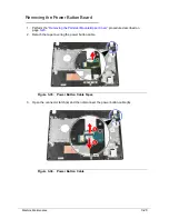
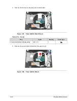
Power Button Board Disassembly
M2 × L3
1
86.00F80.723
Mainboard Disassembly
M2.5 × L6
1
86.00E12.536
Thermal Module Disassembly
–
5
LCD Module Disassembly
M2.5 × L6
4
86.00E12.536
KEYBOARD
BLUETOOTH
MODULE
THERMAL
MODULE
RTC
BATTERY
EXTERNAL MODULES
PALMREST MODULE/
UPPER COVER
POWER
BUTTON
BOARD
SPEAKER
MODULE
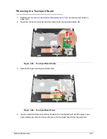
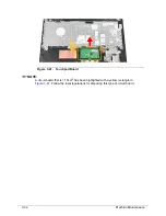
TOUCHPAD
BOARD
MAINBOARD
LCD
MODULE
USB
BOARD
CPU
Summary of Contents for Aspire 4560
Page 1: ... Aspire 4560 4560G SERVICEGUIDE ...
Page 10: ...x ...
Page 11: ...CHAPTER 1 Hardware Specifications ...
Page 14: ...1 4 ...
Page 51: ...CHAPTER 2 System Utilities ...
Page 67: ...CHAPTER 3 Machine Maintenance ...
Page 70: ...3 4 ...
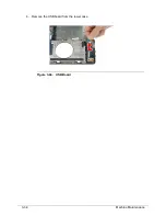
Page 100: ...3 34 Machine Maintenance 4 Remove the USB board from the lower case Figure 3 44 USB Board ...
Page 109: ...Machine Maintenance 3 43 6 Remove the LCD module from the lower cover Figure 3 60 LCD Module ...
Page 162: ...3 96 Machine Maintenance ...
Page 163: ...CHAPTER 4 Troubleshooting ...
Page 193: ...CHAPTER 5 Jumper and Connector Locations ...
Page 200: ...5 8 Jumper and Connector Locations ...
Page 201: ...CHAPTER 6 FRU List ...
Page 202: ...6 2 Aspire 4560 4560G Exploded Diagram 6 4 Main Assembly 6 4 LCD Assembly 6 6 FRU List 6 7 ...
Page 217: ...CHAPTER 7 Model Definition and Configuration ...
Page 218: ...7 2 Aspire 4560 4560G 7 3 ...
Page 325: ...CHAPTER 8 Test Compatible Components ...
Page 326: ...8 2 Microsoft Windows 7 Environment Test 8 4 ...
Page 332: ...8 8 Test Compatible Components ...
Page 333: ...CHAPTER 9 Online Support Information ...
Page 334: ...9 2 Online Support Information 9 3 ...
Page 336: ...9 4 Online Support Information ...

