12
Chapter 1
Touchpad Basics (with fingerprint reader)
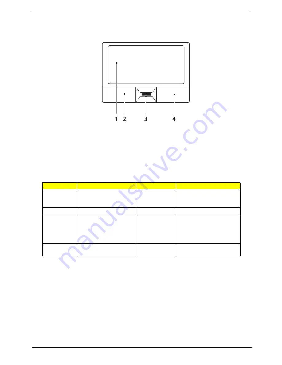
The following items show you how to use the touchpad with Acer Bio-Protection fingerprint reader:
•
Move your finger across the touchpad (1) to move the cursor.
•
Press the left (2) and right (4) buttons located beneath the touchpad to perform selection and
execution functions. These two buttons are similar to the left and right buttons on a mouse.
Tapping on the touchpad is the same as clicking the left button.
•
Use Acer Bio-Protection fingerprint reader (3) supporting Acer FingerNav 4-way control function
(only for certain models) or the 4-way scroll (3) button (only for certain models) to scroll up or down
and move left or right a page. This fingerprint reader or button mimics your cursor pressing on the
right scroll bar of Windows applications.
NOTE:
When using the touchpad, keep it - and your fingers - dry and clean. The touchpad is sensitive to finger
movement; hence, the lighter the touch, the better the response. Tapping too hard will not increase the
touchpad’s responsiveness.
Function
Left Button (2)
Right Button (4)
Main touchpad (1)
Execute
Quickly click twice.
Tap twice (at the same speed
as double-clicking a mouse
button).
Select
Click once.
Tap once.
Drag
Click and hold, then use
finger on the touchpad to
drag the cursor.
Tap twice (at the same speed
as double-clicking a mouse
button); rest your finger on
the touchpad on the second
tap and drag the cursor.
Access
context menu
Click once.
Summary of Contents for Aspire 4740G
Page 6: ...VI ...
Page 10: ...X Table of Contents ...
Page 56: ...46 Chapter 2 ...
Page 63: ...Chapter 3 53 5 Carefully open the HDD Cover ...
Page 65: ...Chapter 3 55 5 Remove two 2 screws from the WLAN bracket and lift it clear of the device ...
Page 90: ...80 Chapter 3 5 Remove the TouchPad Bracket from the Upper Cover ...
Page 92: ...82 Chapter 3 Step Size Quantity Screw Type Media Board M2 5 3 2 ...
Page 97: ...Chapter 3 87 Step Size Quantity Screw Type Bluetooth Module M2 5 3 1 ...
Page 99: ...Chapter 3 89 7 Lift one edge of the mainboard as shown to remove it from the base ...
Page 107: ...Chapter 3 97 4 Lift the bezel away from the panel ...
Page 110: ...100 Chapter 3 4 Lift the LCD Panel out of the casing as shown ...
Page 117: ...Chapter 3 107 13 Ensure that the securing pin is properly located ...
Page 129: ...Chapter 3 119 ...
Page 134: ...124 Chapter 3 4 Turn the computer over Replace the fifteen screws on the bottom panel ...
Page 141: ...Chapter 3 131 4 Turn the computer over and replace the six 6 securing screws as shown ...
Page 186: ...176 Chapter 6 ...
Page 187: ...Chapter 6 177 ...
Page 208: ...Appendix A 198 ...
Page 214: ...204 Appendix B ...
Page 216: ...206 Appendix C ...

