background image

78

Chapter 4

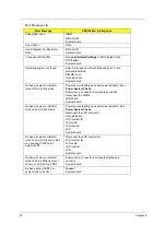
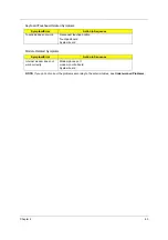
Failing Bits: nnnn

DIMM
BIOS ROM
System board

Fixed Disk n

None

Invalid System Configuration 
Data

BIOS ROM
System board

I/O device IRQ conflict

Run 

Load Default Settings

 in BIOS Setup Utility.

RTC battery
System board

Operating system not found

Enter Setup and see if fixed disk and drive A: are 
properly identified.
Diskette drive
Hard disk drive
System board

No beep, power-on indicator 
turns off and LCD is blank.

Power source (battery pack and power adapter). See 

Power System Check

Ensure every connector is connected correctly. 
Reconnect the DIMM.
LED board
System board

No beep, power-on indicator 
turns on and LCD is blank.

Power source (battery pack and power adapter). See 

Power System Check

Reconnect the LCD connector.
Hard disk drive
LCD inverter ID
LCD cable
LCD Inverter
LCD
System board

No beep, power-on indicator 
turns on and LCD is blank. But 
you can see POST on an 
external CRT. 

Reconnect the LCD connectors.
LCD inverter ID
LCD cable 
LCD inverter
LCD
System board

No beep, power-on indicator 
turns on and a blinking cursor 
shown on LCD during POST.

Ensure every connector is connected tightly and 
correctly.
System board

No beep during POST but 
system runs correctly.

Speaker
System board

Error Message List

Error Message

FRU/Action in Sequence

Summary of Contents for Aspire 5110

Page 1: ...e 5110 5100 3100 TravelMate 5510 5210 Extensa 5410 5010 Service Guide PRINTED IN TAIWAN Service guide files and updates are available on the ACER CSD web For more information please refer to http csd acer com tw ...

Page 2: ...evision History Please refer to the table below for the updates of Aspire 5110 5100 3100 and TravelMate 5510 5210 and Extensa 5410 5010 service guide Date Chapter Updates April 26 2007 New model name added ...

Page 3: ...ublication may be reproduced transmitted transcribed stored in a retrieval system or translated into any language or computer language in any form or by any means electronic mechanical magnetic optical chemical manual or otherwise without the prior written permission of Acer Incorporated ...

Page 4: ...al is sold or licensed as is Should the programs prove defective following their purchase the buyer and not Acer Incorporated its distributor or its dealer assumes the entire cost of all necessary servicing repair and any incidental or consequential damages resulting from any defect in the software Acer is a registered trademark of Acer Incorporated AMD is a registered trademark of AMD Corporation...

Page 5: ... bits and pieces of additional information related to the current topic WARNING Alerts you to any damage that might result from doing or not doing specific actions CAUTION Gives precautionary measures to avoid possible hardware or software problems IMPORTANT Reminds you to do specific actions relevant to the accomplishment of procedures ...

Page 6: ...ill NOT be covered in this generic service guide In such cases please contact your regional offices or the responsible personnel channel to provide you with further technical details 2 Please note WHEN ORDERING FRU PARTS you should check the most up to date information available on your regional web or channel For whatever reason if a part number change is made it will not be noted in the printed ...

Page 7: ...9 Base View 10 Using the Keyboard 11 Lock keys and Embedded Numeric Keypad 11 Windows keys 12 Hotkeys 12 Special keys 13 Indicators 14 Easy launch Buttons 15 Touchpad 16 Touchpad Basics 16 Acer Empowering Technology 18 Empowering Technology Password 18 Acer eDataSecurity Management for selected models 18 Acer eLock Management 20 Acer ePerformance Management 21 Acer eRecovery Management 22 Acer eSe...

Page 8: ...oving the HDD Module 57 Removing the RAM Module Mini PCI Card Thermal Module CPU 58 Removing the ODD Module 60 Removing the LCD Module from the Main Unit 61 Removing the Keyboard 62 Disassembling the Main Unit 63 Disassembling the LCD Module 68 Chapter 4 Troubleshooting 71 System Check Procedures 72 External Diskette Drive Check 72 External CD ROM Drive Check 72 Keyboard or Auxiliary Input Device ...

Page 9: ...4 Undetermined Problems 85 Chapter 5 Jumper and Connector Location 86 Main Board 86 Top Side 86 Bottom Side 88 Switch Board 90 Top Side 90 Bottom Side 91 Chapter 6 FRU Field Replacement Unit List 92 Parts 93 Exploded Diagram 102 ...

Page 10: ... viewing on dual displays via Acer GridVistaTM 15 XGA colour TFT LCD 1024 x 768 pixel resolution Graphics ATI Radeon Xpress 1100 chipset with integrated 3D graphics up to 256MB of shared system memory ATI MobilityTM Radeon X1300 X1600 with up to 512MB of HyperMemoryTM 64MB of dedicated GDDR2 VRAM up to 448MB of shared system memory supporting ATI PowerPlayTM 5 0 Microsoft DirectX 9 0 PCI Express D...

Page 11: ...uble layer drive DVD CD RW combo drive 5 in 1 card reader supporting Secure Digital SD MultiMediaCard MMC Memory Stick MS Memory Stick PROTM MS PRO xD Picture CardTM xD for selected models Communication Acer Video Conference featuring Voice and Video over Internet Protocol VVoIP support via Acer OrbiCamTM and optional Acer Bluetooth VoIP phone for selected models Acer OrbiCamTM integrated 310 000 ...

Page 12: ... VGA port AV in port for selected models RF in jack for selected models S video TV out NTSC PAL port for selected models Headphones speaker line out jack with S PDIF support for selected models Microphone in jack Line in jack Ethernet RJ 45 port Modem RJ 11 port DC in jack for AC adapter Power Subsystem ACPI 2 0 CPU power management standards Stand by and Hibernation power saving modes support 71W...

Page 13: ... 33 8 H mm 14 1 x 10 6 x 1 17 1 33 inches 2 82 kg 6 22 lbs for 15 4 LCD model 2 78 kg 6 13 lbs for 15 LCD model Environment Temperature Operating 5 o C to 35 o C Non operating 20 o C to 65 o C Humidity non condensing Operating 20 to 80 Non operating 20 to 80 ...

Page 14: ...MC RTC CKT 549 BGA AC LINK ATI SB460 AMP Audio Jack Slot 0 BT Conn PATA 5in1 CardReader Slot Mini PCI Socket RJ45 CONN HDD Conn Touch Pad CONN ENE KB910 Int KBD BIOS SATA HDD Conn Conn 1394 1394 Controller VT6311S ALC883 Audio CKT Realtek RTL8100CL SMsC LPC47N207 CDROM Conn MDC Conn USB 2 0 USB 2 0 SATA Clock Generator ICS951462 Thermal Sensor ADM1032ARM DDRII DDRII SO DIMM X2 Dual Channel Socket ...

Page 15: ...use buttons the center button serves as a four way scroll button 5 Palmrest Comfortable support area for your hands when you use the computer 6 Microphone Internal microphone for sound recording 7 TV media volume buttons For use with Acer Arcade and other media playing programs for selected models 8 Easy launch buttons Buttons for launching frequently used programs 9 Status indicators Light Emitti...

Page 16: ...tes the computer s battery status 6 CIR receiver Receives signals from a remote control for selected models 7 Microphone in jack Accepts input from external microphones 8 Line in jack Accepts audio line in devices e g audio CD player stereo walkman 9 Headphones speaker line out jack with S PDIF support Connects to audio line out devices e g speakers headphones 10 N A Latch Locks and releases the l...

Page 17: ...o IEEE 1394 devices optional 8 PC Card slot Accepts one Type II PC Card 9 ExpressCard 34 slot Accepts one ExpressCard 34 module optional 10 N A PC Card slot eject button Ejects the PC Card from the slot Item Description 1 Optical disk drive Internal optical drive accepts CDs or DVDs 2 Optical disk access indicator Lights up when the optical disk drive is active 3 Optical disk drive eject button Ej...

Page 18: ...evice with S video input for selected models 7 External display VGA port Connects to an external display device e g external monitor LCD projector 8 DVI D port Supports digital video connections for selected models 9 USB 2 0 port Connect to USB 2 0 devices e g USB mouse USB camera 10 N A Ventilation slots Enable the computer to stay cool even after prolonged use Icon Item Description Icon Item Des...

Page 19: ...ith screws 2 Memory compartment Houses the computer s main memory 3 Ventilation slots and cooling fan Helps keep the computer cool NOTE Do not cover or obstruct the opening of the fan 4 Battery lock Locks the battery in position 5 Battery bay Houses the computer s battery pack Item Description Note ...

Page 20: ... Lock is on the right hand side numeric keypad is in numeric mode The keys function as a calculator complete with the arithmetic operators and When Num Lock is off the keys assume cursor and other shortcut functions Scroll Lock Fn F12 When Scroll Lock is on the screen moves one line up or down when you press the up or down arrow keys respectively scroll Lock does not work with some applications De...

Page 21: ...M Minimizes all windows Shift M Undoes the minimize all windows action Application key This key has the same effect as clicking the right mouse button It opens the application s context menu Hot Key Icon Function Description Fn F1 Hot key help Displays help on hotkeys Fn F2 Acer eSettings Launches the Acer eSettings in Acer Empowering Technology Fn F3 Acer ePower Management Launches the Acer ePowe...

Page 22: ...language settings Fn F5 Display toggle Switches the display output between the display screen external monitor if connected and both Fn F6 Screen blank Turns off the display screen backlight to save power Press any key to return Fn F7 Touchpad toggle Turns the internal touchpad on and off Fn F8 Speaker toggle Turns the speakers on and off Fn K Volume up Increases the sound volume Fn L Volume down ...

Page 23: ... Num Lock is activated Power Lights when the computer is on Battery Lights when the battery is being charged Bluetooth Indicates the status of Bluetooth communication Wireless LAN Indicates the status of wireless LAN communication Icon Function Description Launch keys on page 10 Icon Item Description Item Description Launch keys on page 10 Icon Item Description Item Description Launch keys on page...

Page 24: ...can be redefined by users To set the web browser mail and programmable buttons run the Acer Launch Manager Easy launch button Default application Acer Empowering Technology user programmable Mail E mail application user programmable Web browser Internet browser user programmable P User programmable Easy launch buttons on page 10 Easy launch buttons on page 10 1 Charging 2 Fully charged Acer Empowe...

Page 25: ...on to scroll up or down and move left or right a page This button mimics your cursor pressing on the right scroll bar of windows applications NOTE Keep your fingers as well as the surface of the touchpad dry and clean The touchpad is sensitive to your finger movements the lighter the touch the better the response Tapping hard will not increase Function Left button 1 Right button 4 Main touchpad 2 ...

Page 26: ...Chapter 1 17 the touchpad s responsiveness NOTE By default vertical and horizontal scrolling is enabled on your touchpad It can be disabled under Mouse settings in Windows Control Panel ...

Page 27: ...logy password you will be prompted to do so when running Acer eLock Management or Acer eRecovery Management for the first time NOTE If you lose your password there is no method to reset it except by reformatting your notebook or taking your notebook to an Acer Customer Service Center Be sure to remember or write down your password Acer eDataSecurity Management for selected models Acer eDataSecurit...

Page 28: ...Chapter 1 19 Be sure to safeguard all related passwords ...

Page 29: ...plugged into the system Optical drive devices includes any kind of CD ROM or DVD ROM drives Floppy disk drives 3 5 inch disks only Interfaces includes serial port parallel port infrared IR and Bluetooth To activate Acer eLock Management a password must be set at first Once set you may apply locks to any of the three kinds of devices Lock s will be set without any reboot necessary and will remain l...

Page 30: ...es an express optimization method to release unused memory and disk space quickly The user can also enable advanced options for full control over the following options Disk optimization removes unneeded items and files Speed optimization improves the usability and performance of the Windows XP system Memory optimization releases unused memory and check usage ...

Page 31: ...set recovery point Backup to CD or DVD Image data recovery tools Recovery from a hidden partition factory defaults Recovery from the HDD most recent user defined recovery point Recovery from CD or DVD NOTE If the computer did not come with a Recovery CD or System CD please use Acer eRecovery Management s System backup to optical disk feature to burn a backup image to CD or DVD To ensure the best r...

Page 32: ... hardware specification change BIOS passwords or other Windows settings and to monitor the system health status Acer eSettings Management also Provides a simple graphical user interface for navigation Displays general system status and advanced monitoring for power users on Acer computer ...

Page 33: ...ice if supported DC Mode Battery Mode There are four pre defined profiles Entertainment Presentation Word Processing and Battery Life You can also define up to three of your own To Create a New Power Profile 1 Change power settings as desired 2 Click Save as to save to a new power profile 3 Name the newly created profile 4 Select whether this profile is for Adapter or Battery mode then click OK 5 ...

Page 34: ... factory defaults Select what actions to be taken when the cover is closed or the power button is pressed Set passwords for accessing the system after Hibernation or Stand by View information about Acer ePower Management ...

Page 35: ...omatically switched out when an external display is connected to the system For projectors and external devices that are not auto detected launch Acer ePresentation Management to choose an appropriate display setting NOTE If the restored resolution is not correct after disconnecting a projector or you need to use an external resolution that is not supported by Acer ePresentation Management adjust ...

Page 36: ...efined display settings so you can view multiple windows on the same screen To access this function please go to Start All Programs and click on Acer GridVista You may choose any one of the four display settings indicated below Acer Gridvista is dual display compatible allowing two displays to be partitioned independently Acer GridVista is simple to set up 1 Run Acer GridVista and select your pref...

Page 37: ...ager Launch Manager allows you to set the four easy launch buttons located above the keyboard You can access the Launch Manager by clicking on Start All Programs Launch Manager to start the application Note Easy launch buttons on page 24 Start All Programs Launch Manager Note Easy launch buttons on page 24 Start All Programs Launch Manager ...

Page 38: ...k bar highlight Programs and select Norton Antivirus 2 In the Norton Antivirus main window click Scans 3 In the Scans panel click Run Full System Scan 4 When the scan is complete a scan summary appears Click Finished You can schedule customized virus scans that tun unattended on specific dates and times or at periodic intervals If you are using the computer when the scheduled scan begins it runs i...

Page 39: ... 64 bit DDR SDRAM at 100 133 166 200MHz HyperTransportTM Technology to I O devices one 16 bit link supporting speed up to 800MHz 1600 MT s or 3 2 GB s in each direction On die second L2 cache 1024KB 512KB System Board Major Chips Item Specification Core logic ATi RS485MC ATi SB460 Super I O controller SMSC SIO1036 Audio controller Codec ALC883 Video controller Integrated VGA solution for ATi RS485...

Page 40: ...HCT0 WD800UE 22HCT0 Formatted Gbytes 512 bytes sector 40 60 80 Physical read write head 2 3 4 Discs 1 2 2 Spindle Speed RPM 4200 5400 5400 I O data transfer rate Mbytes sec max 100 ultra DMA mode 5 100 ultra DMA mode 5 100 ultra DMA mode 5 ATA data transfer mode supported ATA ATAPI 6 ATA 6 ATA ATAPI 6 ATA 6 ATA ATAPI 6 ATA 6 Bytes per sector 512 512 512 Max media transfer rate disk buffer Mbytes s...

Page 41: ...ory Item Description Chip ATi SB460 Feature 256 512 1024MB two 1 8V JEDEC standard 200 pin DDRII SODIMM memory module connectors Adjustable 128MB UMA VGA memory share from system memory VGA Item Description Chip ATi RS485MC Features VGA memory up to 128MB Display core frequency of 200MHz 3D graphics engine Analog display support Dedicated 2FP local flat panel interface single or dual channel LVDS ...

Page 42: ...requency up to 50MHz support 5 Contain two 512 byte buffer to maximize the transfer speed 6 Traffic LED light support 7 Over current protection support Memory Stick Interface 1 Compliant with Memory Stick PRO Format Specification Version 1 0 2 4 bit parallel data transfer mode support 3 Memory stick clock frequency up to 40MHz 4 DMA mode to minimize CPU to overhead 5 Traffic LED light support Smar...

Page 43: ...l array analog microphone Two speakers at least 1W 9cc for each LAN Item Description LAN controller Realtek RTL8100CL Feature 10 100Mbps operation 10 100Mbps WOL from S5 support File deployment support Connector type RJ 45 Wireless LAN Item Description Card type Mini PCI Features 802 11b g Built in two antenna Wi Fi WPA2 WMM CCX V3 and above support To be placed on the top of LCD on the sides of L...

Page 44: ...tal without HW MPEG2 Hybrid LCD 15 4 WXGA Item Specification Vendor Model name QDI QD15AL02 01 QD15AL02 02 QDI QD15TL07 01 QD15TL07 02 LPL LP154W01 TLE1 LP154W01 TLD1 CMO N154I2 L01 N154I2 L02 Screen Diagonal 15 4 WXGA 15 4 WXGA 15 4 WXGA 15 4 WXGA Active area 331 2 W x 207 0 H 331 2 W x 207 0 H 331 2 W x 207 0 H 335 0 W x 210 7 H Display resolution 1680 x 3 RGB x 1050 1280 x 3 RGB x 800 1280 x 3 ...

Page 45: ...262 144 colors LCD 15 XGA Item Specification Vendor Model name QDI QD150XL06 03 01 LPL LP150X08 TLA2 CMO N150X3 L9 AUO B150XG02 V4 Screen Diagonal 15 XGA 15 XGA 15 XGA 15 XGA Active area 304 13 W x 228 1 H 304 128 W x 228 096 H 304 1 W x 228 1 H 304 1 W x 228 1 H Display resolution 1024 x 3 RGB x 768 1024 x 3 RGB x 768 1024 x 3 RGB x 768 1024 x 3 RGB x 768 Display mode normally white normally whit...

Page 46: ... to 265Vac Rated frequency for 50Hz or 60Hz for 50Hz or 60Hz Frequency range from 47Hz to 63Hz from 47Hz to 63Hz Steady AC current less than 1 5A rms at 100Vac input and maximum load less than 1 5A rms at 100Vac input and maximum load Output feature Rated voltage 19V 19V Voltage range 18 05V to 20V from 18 2V to 19 8V Rated power 90 W 90 W Output ripple and noise less than 300mVp p less than 300mV...

Page 47: ...rm 1 and Form 2 CD I Ready Video CD MPEG 1 Karaoke CD PhotoCD Multi Session Enhance CD CD extra I Trax CD and UDF DVD read DVD ROM single layer 4 7GB dual layer 8 5GB DVD R 3 95GB 4 7GB DVD RW 4 7GB DVD RAM 2 6GB 4 7GB CD read CD ROM Mode 1 CD ROM XA CD Audio Mixed Mode CD ROM Audio and Data Combined Photo CD Single and Multi session CD I Video CD CD Plus CD Extra CD Text CD R disc CD RW disc CD w...

Page 48: ...a CD PLUS Video CD CD text data read write CD R read write DVD ROM DVD R read write DVD R DL read write DVD RW read write DVD RW read write DVD R read write DVD R DL read write DVD RW read write DVD RW high speed read write DVD RAM read write DVD read DVD 5 DVD 9 DVD 10 DVD 18 DVD Video DVD Audio SACD Hybrid DVD R DVD R DL DVD R 3 95GB DVD R Authoring DVD R multi border DVD RW DVD R DVD R DL DVD R...

Page 49: ...icable disc format CD DA CD ROM Mode 1 CD ROM XA Mode 2 Form 1 and Mode 2 Form 2 CD I Video CD MPEG 1 CD Text PhotoCD Enhance CD CD extra I Trax CD and UDF DVD ROM DVD Video DVD Audio DVD R single multi border DVD R single multi session DVD RW DVD RW DVD RAM Loading mechanism Load manual load DC brushless motor system Power requirement Max 1500mA Input voltage 5V 5 operating Fan True Value Table F...

Page 50: ...ss m during POST when Press F2 to enter Setup message is prompted on the left bottom side of the screen There are six prime items in the BIOS Setup Utility They are Information Main Advanced Security Boot and Exit In the coming pages we will explain the BIOS Setup Utility by item NOTE During setup all Fn function keys and power saving function are disabled Part Description Information Display the ...

Page 51: ...r This item is the serial number of the system Asset Tag Number This item is the asset tag number of the system UUID It shows only when an internal LAN device is available PhoenixBIOS Setup Utility Info Main Advanced Security Boot Exit CPU Type AMD Turion tm 64 X2 Mobile Technology CPU Speed ATAPI Serial Number System BIOS Version VGA BIOS Version V0 17A ATi 009 012 001 005 EC BIOS Version Serial ...

Page 52: ...l detect if any display device is connected on external video port If any external display device is connected the power on display will be only in CRT or projector mode Otherwise it will be in LCD mode Both Both the integrated LCD and the external video port for an external CRT or projector will be enabled simultaneously Network Boot It permits the users to boot from network PhoenixBIOS Setup Uti...

Page 53: ... it is not enabled device boot priority will not be adjustable during POST The boot device change is only for one time change In other words when the system is rebooted the boot device sequence will be the same as the one defined in the BIOS setup Boot option D2D Recovery It allows the users to enable or disable the disk to disk recovery ...

Page 54: ...IOS or OS chooses configuration PhoenixBIOS Setup Utility Info Main Advanced Security Boot Exit Item Specific Help Infrared Port FIR Advanced Chipset Control Advanced Configuration and Power Interface Debug only remove this option for production En Disable ACPI BIOS F1 Help Select Item F5 F6 Change Values F9 Setup Defaults Esc Exit Select Menu Enter Select 4 Sub Menu F10 Save and Exit Yes Enabled ...

Page 55: ...igned The valid keys are listed in the table below Symbol Character Symbol Name A Z letters A to Z not case sensitive 0 9 numerical characters dash equal sign left bracket PhoenixBIOS Setup Utility Info Main Advanced Boot Item Specific Help Supervisor Password Is Clear User Password Is Clear Enter Set Supervisor Password Password on Boot Disabled Supervisor Password controls accesses of the setup ...

Page 56: ...is enabled the system will pop up the password dialog box to ask for the password when the system is powered on or resumes for S4 state If the users fail three times consecutively in password verification the system will be hung up and the users need to manually power off the system Set Supervisor Password User Password Highlight the item and press Enter a dialog box will be shown to ask the users...

Page 57: ... LAN device PhoenixBIOS Setup Utility Info Main Advanced Security Exit Item Specific Help Boot priority order Keys used to view or configure devices Up and Down arrows select a device then press F1 Help Select Item F5 F6 Change Values F9 Setup Defaults Esc Exit Select Menu Enter Select 4 Sub Menu F10 Save and Exit Boot 1 SATA ST9120821AS S1 2 IDE 1 3 IDE 0 MATSHITADVD RAM UJ 845S PM 4 PCI BEV Real...

Page 58: ...hanges The users can discard previous changes in CMOS Setup Save Changes The users can save current changes in CMOS Setup PhoenixBIOS Setup Utility Info Main Advanced Security Boot Item Specific Help Exit Saving Changes Exit Dicarding Changes Load Setup Defaults Exit System Setup and save your changes to CMOS F1 Help Select Item F5 F6 Change Values F9 Setup Defaults Esc Exit Select Menu Enter Sele...

Page 59: ...50 Chapter 2 DOS Flash SOP 1 Press F2 to enter Setup Menu select Boot page to change boot device priority order Use USB as an example 2 Execute the BIOS BAT or FLASH BAT batch file to update BIOS ...

Page 60: ...Chapter 2 51 3 In flash BIOS the caution message Please do not remove AC power source will show If AC power source is plugged the caution message AC adapter does not exist ...

Page 61: ...52 Chapter 2 4 Flash status will show as following picture When you finish BIOS update the system will shut down or re boot automatically ...

Page 62: ...strap and conductive mat for preventing electrostatic discharge Small Philips screw driver Flat head screw driver Hexagonal driver Tweezers NOTE The screws for the different components vary in size During the disassembly process group the screws with the corresponding components to avoid mismatch when putting back the components When you remove the stripe cover please be careful not to scrape the ...

Page 63: ...ystem are unplugged 3 The battery pack is removed NOTE There are several types of screws used to secure the main unit The screws vary in length Please refer to the screws table after the flowchart Group the same type of screws together during service disassembling Please also remember the screw location for each screw type If you fasten the screws on the wrong location the long screws may cause ir...

Page 64: ...ructs you how to remove the components Screws List No Description Part No a SCREW M2 5 3 NL 86 ADWV5 001 b SCREW M2 5 6 NL 86 ADWV5 002 c SCREW M2 5 10 NL 86 ADWV5 003 d SCREW M2 5 15 NL 86 ADWV5 004 e SCREW M2 2 2 86 ADWV5 005 f SCREW M2 3 B NL 86 ADWV5 006 g SCREW M2 3 S NL 86 ADWV5 007 h SCREW M2 4 86 ADWV5 008 i SCREW M3 4 NL 86 ADWV5 009 ...

Page 65: ...56 Chapter 3 j SCREW D SUB 4 X40 1 5 NI NL 86 ADWV5 010 Screws List No Description Part No ...

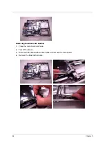
Page 66: ... to the end as the arrow indicates 2 The battery pack will pop up then remove it Removing the HDD Module 1 Release the two screws fastening the HDD module cover 2 Detach the HDD module cover 3 Pull the HDD module then lift the HDD module as the arrow indicates then detach the HDD module ...

Page 67: ... 3 Pull the RAM module locks at the same time as the arrows indicate 4 The RAM module will pop up then detach it Repeat the anterior step to remove another RAM module 5 Pull the Mini PCI card locks at the same time as the arrows indicate 6 The Mini PCI card will pop up then detach it 7 Disconnect the auxiliary antenna cable gray and the main antenna cable black ...

Page 68: ... the system fan cable carefully the remove the system fan 10 Release the four screws securing the CPU heatsink 11 Remove the CPU heatsink as the arrow indicates 12 Counter clockwise release the screw securing the CPU using a flat head screw driver 13 Carefully detach the CPU ...

Page 69: ...remove the anterior components Please skip the anterior steps of disassembly After you remove the battery pack and the thermal module cover follow the steps below 1 Release the screw securing the ODD module 2 Push the ODD module using a screwdriver as shown 3 Remove the ODD module from the main unit ...

Page 70: ...skip all the main unit disassembly procedures After removing the battery pack please follow the steps below 1 Open the notebook as shown 2 Remove the middle cover from the edge of the middle cover 3 Carefully detach the middle cover 4 Carefully disconnect the LCD cable 5 Slightly pull out the wireless antenna cables ...

Page 71: ... Removing the Keyboard If you just want to replace the keyboard skip the LCD module disassembly After you remove the middle cover follow the steps below 1 Release the two screws securing the keyboard plate 2 Carefully detach the keyboard plate from the edge of the keyboard plate and place the keyboard plate as shown 3 Release the keyboard FFC lock carefully because it is fragile Then remove the ke...

Page 72: ...ragile Then disconnect the media board FFC 2 Release the 12 screws securing the upper case and the lower case on the bottom side 3 Release the four hexagonal screws securing the external VGA port and the DVI D port 4 Release the two screws securing the upper case and the lower case on the upper side 5 Then detach the upper case from the main unit ...

Page 73: ...4 Chapter 3 Removing the Power Board and the Modem Board 1 Detach the power board slightly 1 Release the two screws securing the modem board 2 Detach the modem board then disconnect the modem board cable ...

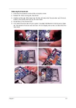
Page 74: ...the edge of the lower case from the left side and at the same time push the main board on the bottom side to pop up the main board 4 Repeat Step 3 from the rear side 5 Then detach the main board If your system is equipped with Bluetooth module please place the main board on the lower case as shown Do not abruptly remove the main board from the lower case ...

Page 75: ...66 Chapter 3 Removing the Bluetooth Module 1 Place the main board as shown 2 Tear off the tinsel 3 Disconnect the Bluetooth module cable and remove the main board 4 Remove the Bluetooth module ...

Page 76: ...e speakers 2 Then detach the speakers Removing the Touch Pad Board 1 Slightly unlock the touch pad FFC lock by nail and disconnect the touch pad FFC 2 Release the screw holding the touch pad board bracket then remove the touch pad board bracket 3 Detach the touch pad board ...

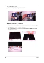
Page 77: ...A heatsink Disassembling the LCD Module 1 Remove the four screw cushions on the LCD bezel then release the four screws holding the LCD bezel 2 Carefully detach the LCD bezel from the LCD module 3 Tear off the tapes holding the LVDS cable and the LCD cable then release the two screws securing the inverter board ...

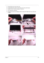
Page 78: ... cable 5 Carefully disconnect the LCD cable then remove the inverter board 6 Release the two screws securing the LCD panel 7 Then detach the LCD panel 8 Release the eight screws holding the left and right LCD brackets and remove the LCD brackets ...

Page 79: ...70 Chapter 3 9 Tear off the tape holding the LCD cable 10 Carefully pull and disconnect the LCD cable ...

Page 80: ...tended to test only Acer products Non Acer products prototype cards or modified options may occur errors or invalid responses 1 Obtain the detailed fail symptoms as many as possible 2 Verify the symptoms by attempting to recreate running the diagnostic tests or repeating the same operation Troubleshooting Chapter 4 ...

Page 81: ...e that the CD ROM does not have any label attached The label may cause damage to the drive or make the drive fail 1 Boot from the diagnostic diskette and start the diagnostic programs 2 See if CD ROM test is passed when the programs run the CD ROM test 3 Follow the instructions in the message window If errors occur reconnect the connector on the system board If the errors still remain 1 Reconnect ...

Page 82: ...aptor and install the battery pack then check the power supply If you think there is a power supply problem please go to Check the Power Adaptor and Check the Battery Pack in this chapter Check the Power Adaptor Unplug the power adaptor cable from the computer and measure the output voltage at the plug of the power adaptor cable See the illustration and follow the procedures below 1 If the voltage...

Page 83: ... 2 Remove the battery pack and measure the voltage between terminals one and seven There are seven terminals totally See the illustration below 3 If the voltage is still less than 7 5V after recharging replace the battery If the battery status indicator does not light up remove the battery pack After the battery pack returns to room temperature reinstall it to the system If the charge indicator do...

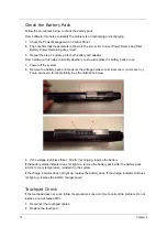
Page 84: ...m board After you use the touchpad the pointer drifts on the screen for a short time This self acting pointer movement will occur when a slight steady pressure is applied to the touchpad pointer This symptom is not a hardware problem ...

Page 85: ...tup defaults to correct the errors Index of Error Messages Error Code List Error Code Error Message 006 Equipment Configuration Error Causes 1 CPU BIOS Update Code Mismatch 2 IDE Primary Channel Master Drive Error The causes will be shown before Equipment Configuration Error 010 Memory Error at xxxx xxxx xxxxh R xxxxh W xxxxh 070 Real Time Clock Error 071 CMOS Battery Bad 072 CMOS Checksum Error 1...

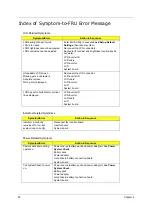
Page 86: ...t system System board Previous boot incomplete Default configuration used Run Load Default Settings in BIOS Setup Utility RTC battery System board Memory size found by POST differed from CMOS Run Load Default Settings in BIOS Setup Utility DIMM System board Diskette drive A error Check the drive is defined with the proper diskette type in BIOS Setup Utility See External Diskette Drive Check Incorr...

Page 87: ... correctly Reconnect the DIMM LED board System board No beep power on indicator turns on and LCD is blank Power source battery pack and power adapter See Power System Check Reconnect the LCD connector Hard disk drive LCD inverter ID LCD cable LCD Inverter LCD System board No beep power on indicator turns on and LCD is blank But you can see POST on an external CRT Reconnect the LCD connectors LCD i...

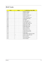
Page 88: ...M E7h Go to BIOS E8h Set Huge Segment E9h Initialize Multi Processor EAh Initialize OEM special code EBh Initialize PIC and DMA ECh Initialize Memory type EDh Initialize Memory size EEh Shadow Boot Block EFh System memory test F0h Initialize interrupt vectors F1h Initialize Run Time Clock F2h Initialize video F3h Initialize System Management Mode F4h 1 Output one beep before boot F5h Boot to Mini ...

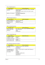
Page 89: ... LCD inverter ID LCD cable LCD inverter LCD System board LCD has extra horizontal or vertical lines displayed LCD inverter ID LCD inverter LCD cable LCD System board Indicator Related Symptoms Symptom Error Action in Sequence Indicator incorrectly remains off or on but system runs correctly Reconnect the inverter board Inverter board System board Power Related Symptoms Symptom Error Action in Sequ...
Page 90: ...BIOS Setup Utility to execute Load Default Settings then reboot system DIMM System board Speaker Related Symptoms Symptom Error Action in Sequence In Windows multimedia programs no sound comes from the computer Audio driver Speaker System board Internal speakers make noise or emit no sound Speaker System board Power Management Related Symptoms Symptom Error Action in Sequence The system will not e...
Page 91: ...match the installed devices Enter BIOS Setup Utility to execute Load Default Settings then reboot system Reconnect hard disk CD ROM diskette drives External display does not work correctly Press Fn F5 LCD CRT Both display switching System board USB does not work correctly System board Print problems Ensure the Parallel Port in the Onboard Devices Configuration of BIOS Setup Utility is set to Enabl...

Page 92: ...ined Problems Touchpad does not work Reconnect touchpad cable Touchpad board System board Modem Related Symptoms Symptom Error Action in Sequence Internal modem does not work correctly Modem phone port modem combo board System board Keyboard Touchpad Related Symptoms Symptom Error Action in Sequence ...
Page 93: ...arge or software errors FRU replacement should be considered only when a recurring problem exists When analyzing an intermittent problems follow the procedures below 1 Run the advanced diagnostic test for the system board in loop mode at least 10 times 2 If no error is detected do not replace any FRU 3 If any error is detected replace the FRU Rerun the test to verify that there are no more errors ...

Page 94: ...e the failing FRU Do not isolate non defective FRU 1 Power off the computer 2 Visually check the devices If any problems are found replace the FRU 3 Remove or disconnect all of the following devices Non Acer devices Printer mouse and other external devices Battery Pack Hard disk drive DIMM CD ROM Diskette drive module PC cards 4 Power on the computer 5 Determine if the problem has been resolved 6 ...

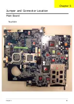
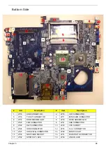
Page 95: ...Chapter 5 86 Main Board Top Side Jumper and Connector Location Chapter 5 ...

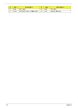
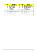
Page 96: ...IA BOARD CONNECTOR 5 JP6 TOUCH PAD BOARD CONNECTOR 6 JP7 INTERNAL KEYBOARD CONNECTOR 7 JP9 PCMCIA SOCKET 8 JP12 INTERNAL SPEAKER CONNECTOR 9 JP13 INTERNAL MIC CONNECTOR 10 U12 LAN CHIP 11 U14 1349 CHIP 12 U17 BIOS FLASH ROM 13 U18 SOUTH BRIDGE CHIP 14 U25 SUPER I O 15 U27 EC KBC CHIP 16 U30 CARD BUS CONTROLLER 17 U33 AUDIO CODEC ...

Page 97: ...CARD CONNECTOR 5 JP18 DDRII SODIMM SLOT 6 JP19 DDRII SODIMM SLOT 7 JP20 FAN CONNECTOR 8 JP21 USB CONNECTOR 9 JP22 RJ45 CONNECTOR 10 JP23 CPU SOCKET 11 JP24 ODD CONNECTOR 12 JP25 5 in 1 CONNECTOR 13 JP27 HDD PATA CONNECTOR 14 JP28 MINI PCI SLOT 15 JP30 NEW CARD SOCKET 16 JP31 BLUETOOTH CONNECTOR 17 JP32 SPDIF OUT JACK 18 JP33 LINE IN JACK ...

Page 98: ...89 Chapter 5 19 JP34 MIC JACK 20 PJP1 DC JACK 21 PJP2 BATTERY PACK CONNECTOR 22 U39 NORTH BRIDGE Item Description Item Description ...

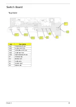
Page 99: ...apter 5 90 Switch Board Top Side Item Description SW1 POWER BUTTON SW2 E MAIL BUTTON SW3 INTERNAL BUTTON SW4 USER BUTTON SW5 EMPOWER BUTTON D1 POWER LED D2 MEDIA LED D3 CAPS LED D4 NUMLK LED D5 EMAIL LED ...

Page 100: ...91 Chapter 5 Bottom Side Item Description JP2 USB CONNECTOR JP3 USB CONNECTOR JP7 LED BOARD CONNECTOR ...

Page 101: ...Chapter 5 92 Clear CMOS You can short JOPEN1 jump on the main board to erase CMOS data Please refer to the images below for the location of JOPEN1 jump ...

Page 102: ...part number is changed it will NOT be noted on the printed service guide For Acer authorized service providers your Acer office may have a different part number code from those given in the FRU list of this printed service guide You MUST use the local FRU list provided by your regional Acer office to order FRU parts for service NOTE To scrap or to return the defective parts you should follow the l...

Page 103: ...00MAH SONY BT 00604 008 BATTERY LI ION 8 CELLS 4800MAH SONY BT 00804 012 BATTERY LI ION 8 CELLS 4800MAH SANYO BT 00803 015 BOARD MODEM BOARD FOXCONN T60M845 02 SV92A1Z AC97 Azalia 54 ABHV5 001 BLUETOOTH MODULE FOXCONN T60H928 01 Broadcom BCM2045 54 ABHV5 002 MINI PCI WIRELESS BOARD FOXCONN ATHEROS 802 11b g T60N874 03 AR2414 AR5413 solution 54 ABHV5 003 N A MINI PCI WIRELESS BOARD FOXCONN BROADCOM...

Page 104: ... WIRESET 15 IN 50 ABHV5 007 N A LCD WIRESET 15 4 IN 50 ABHV5 008 POWER CORD N A POWER CORD US 3 PIN 27 TAVV5 001 N A POWER CORD EU 3 PIN 27 TAVV5 002 N A POWER CORD AUS 3 PIN 27 TAVV5 003 N A POWER CORD UK 3 PIN 27 TAVV5 004 N A POWER CORD CHINA 3 PIN 27 TAVV5 005 N A POWER CORD SWISS 3 PIN 27 TAVV5 006 N A POWER CORD ITALIAN 3 PIN 27 TAVV5 007 N A POWER CORD DENMARK 3 PIN 27 TAVV5 008 N A POWER C...

Page 105: ...R MIC W O TV DVI 1394 FIR 60 ABHV5 002 THERMAL DOOR 42 ABHV5 002 T P BRACKET 33 ABHV5 001 N A OPTICAL BRACKET 33 ABHV5 002 OPTICAL BEZEL GBASE SUPER MULTI 42 ABHV5 003 N A OPTICAL BEZEL GBASE DVD CDRW 42 ABHV5 005 HDD DOOR AS 42 ABHV5 004 HDD BRACKET 33 ABHV5 003 LCD COVER 15 IN WITH LOGO W ANTENNA 60 ABHV5 003 LCD BEZEL W LOGO 15 IN 60 ABHV5 004 LCD BRACKET SET R L 15IN 6K ABHV5 001 Category Part...

Page 106: ...CM KC S3502 25F COMBO DRIVE DVD CDRW 24X COMBO MODULE 6M ABHV5 001 N A DVD CDRW COMBO 24X DRIVE LITEON SSC 2485K GBASE LF EMI 2 KO 02409 022 N A DVD CDRW COMBO 24X DRIVE PHILIPS SCB5265 GB LF FW TX13 KO 02408 011 N A DVD SUPER MULTI MODULE 6M ABHV5 002 N A DVD SUPER MULTI PIONEER DVR K16RS BASE KU 00805 029 N A DVD SUPER MULTI PANASONIC UJ 850B GBASE LF KU 00807 025 N A DVD SUPER MULTI HLDS GMA 40...

Page 107: ... 08001 023 N A HDD SATA 80G 5400RPM TOSHIBA Aries B MK8032GSX KH 08004 005 N A HDD SATA 80G 5400RPM HGST Moraga B HTS541080G9SA00 KH 08007 015 N A HDD SATA 100G 5400RPM SEAGATE Mercury 2 ST9100824AS FW 3 06 KH 10001 008 N A HDD SATA 100G 5400RPM TOSHIBA Aries B MK1032GSX F W AS021G KH 10004 003 N A HDD SATA 100G 5400RPM HGST Moraga B HTS541010G9SA00 FW S60D KH 10007 005 N A HDD SATA 100G 5400RPM S...

Page 108: ...7 001 N A KEYBOARD THAILAND W O MEDIA B AS KB ASP07 003 N A KEYBOARD HEBREW W O MEDIA B AS KB ASP07 023 N A KEYBOARD ARABIAN W O MEDIA B AS KB ASP07 018 N A KEYBOARD US INTERNATIONAL W O MEDIA B AS KB ASP07 002 N A KEYBOARD RUSSIA W O MEDIA B AS KB ASP07 014 N A KEYBOARD GREEK W O MEDIA B AS KB ASP07 021 N A KEYBOARD CZECH REPUBLIC W O MEDIA B AS KB ASP07 012 N A KEYBOARD UK W O MEDIA B AS KB ASP0...

Page 109: ...HV5 004 N A ASSY LCD MODULE 15 4 IN WXGA NON CLARE W ANTENNA TBD N A LCD 15 4 WXGA QDI QD15TL07 01 NON GLARE LF LK 15409 008 N A LCD 15 4 IN WXGA QDI QD15TL07 02 GLARE LF 16MS LK 15409 009 N A LCD 15 4 WXGA SAMSUNG LTN154XA L01 0 100 25MS L6 G5 NON GLARE 16MS 200 nits LK 15406 016 N A LCD 15 4 IN WXGA SAMSUNG LTN154XA L01 G GLARE 200NITS 16MS LK 15406 017 N A LCD 15 4 IN WXGA LPL LP154W01 TLD1 GLA...

Page 110: ...KET 20 ABHV5 001 MEMORY MEMORY 256MB DDR II 533 NANYA NT256T64UH4A1FN 37B KN 25603 029 N A MEMORY 256MB DDR II 533 MICRON MT4HTF3264HY 53EB4 KN 25604 030 N A MEMORY 256MB DDR II 533 SAMSUNG M470T3354CZ3 CD5 KN 2560B 017 N A MEMORY 256MB DDR II 533 HYNIX HYMP532S64BP6 C4 KN 2560G 012 N A MEMORY 512MB DDR II 533 NANYA NT512T64UH8A1FN 37B KN 51203 023 N A MEMORY 512MB DDR II 533 SAMSUNG M470T6554CZ3 ...

Page 111: ...SMK LC MCE05 001 N A MCE REMOTE CONTROLLER RECEIVER SMK LC MCE05 002 N A MCE IR BLASTER SMK LC MCE05 003 SCREW N A SCREW M2 5 3 NL 86 ADWV5 001 N A SCREW M2 5 6 NL 86 ADWV5 002 N A SCREW M2 5 10 NL 86 ADWV5 003 N A SCREW M2 5 15 NL 86 ADWV5 004 N A SCREW M2 2 2 86 ADWV5 005 N A SCREW M2 3 B NL 86 ADWV5 006 N A SCREW M2 3 S NL 86 ADWV5 007 N A SCREW M2 4 86 ADWV5 008 N A SCREW M3 4 NL 86 ADWV5 009 ...

Page 112: ...ABHV5 004 251 MAINBOARD M52P64MB DISCRETE PATA 10 100 W CARD READER W O MEDIA MB ABJ02 001 252 SWITCH BOARD W TV AS 55 ADWV5 003 253 UPPER CASE AS W O TV MEDIA B 60 ABHV5 001 301 THERMAL DOOR 42 ABHV5 002 304 CPU THERMAL MODULE DIS 60 ABHV5 009 305 FAN ASSY DISCRETE 23 ADWV5 001 308 SCREW M2 3 S NL 86 ADWV5 007 309 SCREW M2 5 10 NL 86 ADWV5 003 310 SCREW M2 5 15 NL 86 ADWV5 004 ...

Page 113: ......

Reviews: