24
Chapter 1
Audio Interface
Battery
Item
Specification
Audio Controller
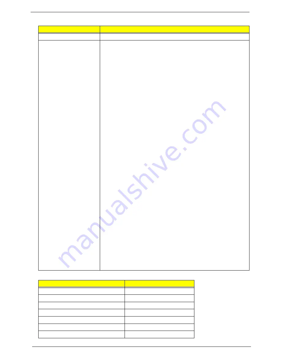
Realtek ALC268S for High Definition Audio Codec
Features
•
High-performance DACs with 97dB SNR (A-Weighting), ADCs with
90dB SNR (A-Weighting)
•
Meets premium performance requirements for Microsoft WLP 3.0x and
future requirement
•
Ten DAC channels support 16/20/24-bit PCM format for 7.1 sound
playback, plus 2channels of independent stereo sound output (multiple
streaming) through the front panel output
•
2 stereo ADCs support 16/20/24-bit PCM format recording
simultaneously.
•
All DACs supports 16/20/24-bit, 44.1k/48k/96k/192kHz sample rate
•
All ADCs supports 16/20/24-bit, 44.1k/48k/96k/192kHz sample rate
•
Two independent S/PDIF-OUT converters support 16/20/24-bit,44.1k/
48k/88.2k/96k/192kHz sample rate
•
High-quality analog differential CD input
•
Supports external PCBEEP input, built-in digital BEEP generator, and
pass through function in D3 mode.
•
Software selectable 2.5V/3.75V/4.7V VREFOUT
•
Two jack detection pins each designed to detect up to 4 jacks
•
Extra jack detection pin for CD input when it is used as an optional line
level input, S/PDIF input and output
•
Support legacy analog mixer architecture
•
Wide range (-80dB ~ +42dB) volume control with 1.5dB resolution of
analog to analog mixer gain
•
Software selectable boost gain (+10/+20/+30dB) for analog
microphone input
•
All analog jacks are stereo input and output re-tasking for analog plug
& play
•
Built-in headphone amplifiers for each re-tasking jack
•
Two GPIOs (General Purpose Input and Output) for customized
applications
•
Supports Anti-pop mode when analog power AVDD is on and digital
power is off
•
Support stereo digital microphone interface to improve voice quality
•
Integrates high pass filter to cancel DC offset generated from digital
microphone
•
48-pin LQFP 'Green' package
•
Support low voltage IO for HDA Link (1.5V~3.3V)
Item
Specification
Vendor & model name
Battery Type
Pack capacity
Number of battery cell
Package configuration
Normal voltage
Charge voltage
Summary of Contents for Aspire 5230
Page 6: ...VI ...
Page 14: ...4 Chapter 1 System Block Diagram ...
Page 64: ...52 Chapter 3 6 Remove the HDD cover as shown 7 Remove the WLAN cover as shown ...
Page 85: ...Chapter 3 73 6 Turn the upper cover over The upper cover appears as follows ...
Page 106: ...94 Chapter 3 7 Lift the Thermal Module clear of the Mainboard ...
Page 112: ...100 Chapter 3 6 Disconnect the left and right Inverter board cables as shown ...
Page 126: ...114 Chapter 3 3 Replace the RJ 11 cable in its housing ...
Page 137: ...Chapter 3 125 2 Replace the bracket as shown 3 Replace the single securing screw ...
Page 140: ...128 Chapter 3 2 Connect the seven cables on the mainboard as shown B C D E F G A ...
Page 152: ...140 Chapter 3 ...
Page 193: ...Chapter 6 181 ...
Page 200: ...188 Appendix B ...
Page 202: ...190 Appendix C ...
Page 205: ...193 Windows 2000 Environment Test 184 Wireless Function Failure 154 WLAN Board 54 ...
Page 206: ...194 ...


