30
Chapter 2
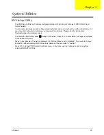
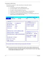
Navigating the BIOS Utility
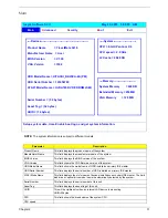
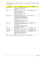
There are six menu options: Info., Main, System Devices, Security, Boot, and Exit.
Follow these instructions:
T
To choose a menu, use the cursor left/right keys (
zx
).
T
To choose a parameter, use the cursor up/down keys (
wy
).
T
To change the value of a parameter, press
p
or
q
.
T
A plus sign (+) indicates the item has sub-items. Press
e
to expand this item.
T
Press
^
while you are in any of the menu options to go to the Exit menu.
T
In any menu, you can load default settings by pressing
t
. You can also press
u
to save any
changes made and exit the BIOS Setup Utility.
NOTE:
You can change the value of a parameter if it is enclosed in square brackets. Navigation keys for a
particular menu are shown on the bottom of the screen. Help for parameters are found in the Item
Specific Help part of the screen. Read this carefully when making changes to parameter values.
Please
note that system information vary in models
.
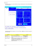
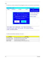
Insyde Software SCU May 20, 2003 5:40:09 AM
Main
A
dvanced
S
ecurity
B
oot E
x
it
----Devices---------------------------------------------------
-----System-------------------------
Product Name = TravelMate 3210
CPU = Intel® Pentium ® 4
Manufacture Name = Acer
CPU speed = 2.0 GHz
BIOS Version = V1.00
L2 Cache = 2048 KB
VGA Version = 3104
HDD Model Name = HITACHI_DK23EA-40-(PM)
HDD Serial Number = 123456789
----Memory------------------------
ATAPI Model Name = UJDA740 DVD/CDROM-(SM)
System Memory = 640 KB
Extended Memory = 256MB
Serial Number = ( 32 bytes)
VGA Memory = 128 MB
Asset Tag = (32 bytes)
UUID = (16 bytes)
Setup system date, time. Enable boot logo and get system information.
Summary of Contents for Aspire 5500
Page 6: ...VI ...
Page 14: ...6 Chapter 1 JP23 Modem Cable Connector JP39 ODD Connector ...
Page 36: ...28 Chapter 1 ...
Page 48: ...40 Chapter 2 ...
Page 57: ...Chapter 3 49 ...
Page 81: ...Chapter 5 73 JP19 RJ11 RJ45 JP31 DDR2 Socket JP23 Modem Cable Connector JP39 ODD Connector ...
Page 82: ...74 Chapter 5 ...
Page 84: ...76 Chapter 6 Exploded Diagram The System 011 012 013 ...
Page 85: ...Chapter 6 77 Upper Case Assembly ...
Page 86: ...78 Chapter 6 Lower Case Assembly ...
Page 87: ...Chapter 6 79 LCD Module ...
Page 88: ...80 Chapter 6 HDD Module ODD Module ...
Page 103: ...Index 104 ...

