Chapter 1
23
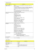
Applicable disc format for
Panasonic UJ-845
Read:
DVD: DVD-5, 9,10,18, DVD-R (3.95G/4.7G), DVD-RW, DVD_RAM (4.7G),
DVD+R, DVD+RW
CD: CD-Audio, CD-ROM (mode1 and mode 2), CD-ROM XA (mode 2, form 1
and form 2), CD-I (mode 2, form 1 and form 2), CD-I Ready, CD-I Bridge, CD-R,
CD-RW, Photo CD, Video CD, Enhanced Music CD, CD-TEXT
Write:
DVD: DVD-RAM, DVD-R4.7GB, DVD-RW, DVD+R, DVD+RW
CD: CD-R, CD-RW (disc at once, sessionat once, track at once, fixed/variable
packet writing, multi-session)
Applicable disc format for Pioneer
DVR-K15RA
KODAK Photo CD Single and Multi-session
CD Extra (CD PLUS)
Video CD
CD text data (Read / Write)
CD-R discs (Read / Write)
CD-RW discs (Read / Write)
DVD-ROM
DVD-R Ver.2.00 for General (Read / Write)
DVD-R-DL (Read/Write)
DVD-RW Ver.1.0 & 1.1 & 1.2 (Read / Write)
DVD+R Ver.1.0 & 1.11& 1.2 (Read/Write)
DVD+R -DL Ver1.0 (Read / Write)
DVD+RW Ver.1.1 & 1.2 (Read/Write)
DVD-RAM (Ver.2.0 & 2.1) (Read only)
Applicable disc format for Pioneer
DVR-K05RA
KODAK Photo CD Single and Multi-session
CD Extra (CD PLUS)
Video CD
CD text data (Read / Write)
CD-R discs (Read / Write)
CD-RW discs (Read / Write)
DVD-ROM
DVD-R Ver.2.00 for General (Read / Write)
DVD-RW Ver.1.0 & 1.1 & 1.2 (Read / Write)
DVD+R Ver.1.0 & 1.11& 1.2 (Read/Write)
DVD+R -DL Ver1.0 (Read / Write)
DVD+RW Ver.1.1 & 1.2 (Read/Write)
DVD-RAM (Ver.2.0 & 2.1) (Read only)
Loading mechanism
Load: Manual (SOSW-833S/DVR-K15)
Auto (UJ-845/DVR-K05)
Release: (a) Electrical Release (Release Button)
(b) Release by ATAPI command
(c) Emergency Release (Except for UJ-845/DVR-K05)
Power Requirement
Input Voltage
5 V +/- 5 % (Operating)
Audio Interface
Item
Specification
Audio Controller
ALC250
Audio onboard or optional
Built-in
Mono or Stereo
Stereo
Resolution
18 bit stereo digital to analog converter
18 bit stereo analog to digital converter
Compatibility
AC97
DVD-Dual Interface
Item
Specification
Summary of Contents for Aspire 5500Z Series
Page 6: ...VI ...
Page 14: ...6 Chapter 1 JP23 Modem Cable Connector JP39 ODD Connector ...
Page 36: ...28 Chapter 1 ...
Page 48: ...40 Chapter 2 ...
Page 57: ...Chapter 3 49 ...
Page 81: ...Chapter 5 73 JP19 RJ11 RJ45 JP31 DDR2 Socket JP23 Modem Cable Connector JP39 ODD Connector ...
Page 82: ...74 Chapter 5 ...
Page 84: ...76 Chapter 6 Exploded Diagram The System 011 012 013 ...
Page 85: ...Chapter 6 77 Upper Case Assembly ...
Page 86: ...78 Chapter 6 Lower Case Assembly ...
Page 87: ...Chapter 6 79 LCD Module ...
Page 88: ...80 Chapter 6 HDD Module ODD Module ...
Page 103: ...Index 104 ...

