Chapter 2
31
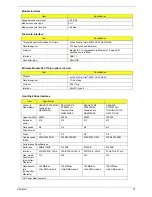
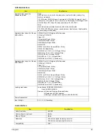
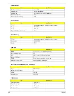
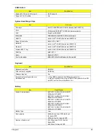
Main
NOTE:
The system information is subject to different models.
Parameter
Description
Product Name
This field displays the prodcut name of the system.
Manufacturer Name
This field displays the manufacturer name of the system
BIOS Version
This field displays the BIOS version of the system.
VGA Version
This field shows the VGA firmware version of the system.
HDD Model Name
This field shows the model name of HDD installed on primary IDE master.
HDD Serial Number
This field displays the serial number of HDD installed on primary IDE master.
ATAPI Mode Name
This field displays the mofel name of devices installed on secondary IDE master. The hard
disk drive or optical drive model name is automatically detected by the system.
Serial Number
This field displays the serial number of this unit.
Asset Tag
This field displays the asset tag of this unit.
UUID
This will be visible only when an internal LAN device is presenting.
UUID=32bytes
CPU
This field shows the brand name of the system CPU.
CPU speed
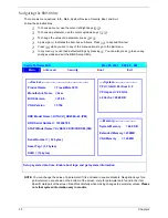
Insyde Software SCU May 20, 2005 5:40:09 AM
Main
A
dvanced
S
ecurity
B
oot E
x
it
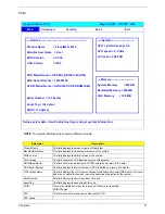
----Devices---------------------------------------------------
-----System-------------------------
Product Name = TravelMate 3210
CPU = Intel® Pentium ® 4
Manufacturer Name = Acer
CPU speed = 2.0 GHz
BIOS Version = V1.00
L2 Cache = 2048 KB
VGA Version = 3104
HDD Model Name = HITACHI_DK23EA-40-(PM)
HDD Serial Number = 123456789
----Memory------------------------
ATAPI Model Name = UJDA740 DVD/CDROM-(SM)
System Memory = 640 KB
Extended Memory = 256MB
Serial Number = ( 32 bytes)
VGA Memory = 128 MB
Asset Tag = (32 bytes)
UUID = (16 bytes)
Setup system date, time. Enable boot logo and get system information.
Summary of Contents for Aspire 5500Z Series
Page 6: ...VI ...
Page 14: ...6 Chapter 1 JP23 Modem Cable Connector JP39 ODD Connector ...
Page 36: ...28 Chapter 1 ...
Page 48: ...40 Chapter 2 ...
Page 57: ...Chapter 3 49 ...
Page 81: ...Chapter 5 73 JP19 RJ11 RJ45 JP31 DDR2 Socket JP23 Modem Cable Connector JP39 ODD Connector ...
Page 82: ...74 Chapter 5 ...
Page 84: ...76 Chapter 6 Exploded Diagram The System 011 012 013 ...
Page 85: ...Chapter 6 77 Upper Case Assembly ...
Page 86: ...78 Chapter 6 Lower Case Assembly ...
Page 87: ...Chapter 6 79 LCD Module ...
Page 88: ...80 Chapter 6 HDD Module ODD Module ...
Page 103: ...Index 104 ...

