58
Chapter 4
Check the Power Adapter
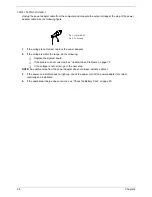
Unplug the power adapter cable from the computer and measure the output voltage at the plug of the power
adapter cable. See the following figure
1.
If the voltage is not correct, replace the power adapter.
2.
If the voltage is within the range, do the following:
T
Replace the System board.
T
If the problem is not corrected, see “Undetermined Problems” on page 70.
T
If the voltage is not correct, go to the next step.
NOTE:
An audible noise from the power adapter does not always indicate a defect.
3.
If the power-on indicator does not light up, check the power cord of the power adapter for correct
continuity and installation.
4.
If the operational charge does not work, see “Check the Battery Pack” on page 59.
Pin 1: +19 to +20.5V
Pin 2: 0V, Ground
Summary of Contents for Aspire 5500Z Series
Page 6: ...VI ...
Page 14: ...6 Chapter 1 JP23 Modem Cable Connector JP39 ODD Connector ...
Page 36: ...28 Chapter 1 ...
Page 48: ...40 Chapter 2 ...
Page 57: ...Chapter 3 49 ...
Page 81: ...Chapter 5 73 JP19 RJ11 RJ45 JP31 DDR2 Socket JP23 Modem Cable Connector JP39 ODD Connector ...
Page 82: ...74 Chapter 5 ...
Page 84: ...76 Chapter 6 Exploded Diagram The System 011 012 013 ...
Page 85: ...Chapter 6 77 Upper Case Assembly ...
Page 86: ...78 Chapter 6 Lower Case Assembly ...
Page 87: ...Chapter 6 79 LCD Module ...
Page 88: ...80 Chapter 6 HDD Module ODD Module ...
Page 103: ...Index 104 ...


