Chapter 4
61
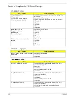
Index of Error Messages
Error Code List
Error Codes
Error Messages
006
Equipment Configuration Error
Causes:
1. CPU BIOS Update Code Mismatch
2. IDE Primary Channel Master Drive Error
(THe causes will be shown before “Equipment Configuration
Error”)
010
Memory Error at xxxx:xxxx:xxxxh (R:xxxxh, W:xxxxh)
070
Real Time Clock Error
071
CMOS Battery Bad
072
CMOS Checksum Error
110
System disabled.
Incorrect password is specified.
<No error code>
Battery critical LOW
In this situation BIOS will issue 4 short beeps then shut down
system, no message will show.
<No error code>
Thermal critical High
In this situation BIOS will shut down system, not show message.
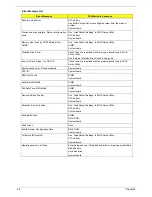
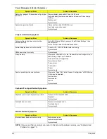
Error Message List
Error Messages
FRU/Action in Sequence
Failure Fixed Disk
Reconnect hard disk drive connector.
“Load Default Settings” in BIOS Setup Utility.
Hard disk drive
System board
Stuck Key
see “Keyboard or Auxiliary Input Device Check” on page 56.
Keyboard error
see “Keyboard or Auxiliary Input Device Check” on page 56.
Keyboard Controller Failed
see “Keyboard or Auxiliary Input Device Check” on page 56.
Keyboard locked - Unlock key switch
Unlock external keyboard
Monitor type does not match CMOS - Run Setup Run “Load Default Settings” in BIOS Setup Utility.
Shadow RAM Failed at offset: nnnn
BIOS ROM
System board
System RAM Failed at offset: nnnn
DIMM
System board
Extended RAM Failed at offset: nnnn
DIMM
System board
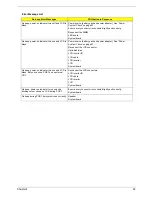
System battery is dead - Replace and run Setup
Replace RTC battery and Run BIOS Setup Utility to reconfigure
system time, then reboot system.
System CMOS checksum bad - Default
configuration used
RTC battery
Run BIOS Setup Utility to reconfigure system time, then reboot
system.
System timer error
RTC battery
Run BIOS Setup Utility to reconfigure system time, then reboot
system.
System board
Summary of Contents for Aspire 5500Z Series
Page 6: ...VI ...
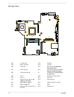
Page 14: ...6 Chapter 1 JP23 Modem Cable Connector JP39 ODD Connector ...
Page 36: ...28 Chapter 1 ...
Page 48: ...40 Chapter 2 ...
Page 57: ...Chapter 3 49 ...
Page 81: ...Chapter 5 73 JP19 RJ11 RJ45 JP31 DDR2 Socket JP23 Modem Cable Connector JP39 ODD Connector ...
Page 82: ...74 Chapter 5 ...
Page 84: ...76 Chapter 6 Exploded Diagram The System 011 012 013 ...
Page 85: ...Chapter 6 77 Upper Case Assembly ...
Page 86: ...78 Chapter 6 Lower Case Assembly ...
Page 87: ...Chapter 6 79 LCD Module ...
Page 88: ...80 Chapter 6 HDD Module ODD Module ...
Page 103: ...Index 104 ...

