66
Chapter 4
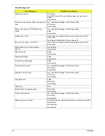
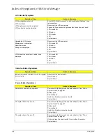
Index of Symptom-to-FRU Error Message
LCD-Related Symptoms
Symptom / Error
Action in Sequence
LCD backlight doesn't work
LCD is too dark
LCD brightness cannot be adjusted
LCD contrast cannot be adjusted
Enter BIOS Utility to execute “Load Setup Default Settings”, then
reboot system.
Reconnect the LCD connectors.
Keyboard (if contrast and brightness function key doesn't work).
LCD inverter ID
LCD cable
LCD inverter
LCD
System board
Unreadable LCD screen
Missing pels in characters
Abnormal screen
Wrong color displayed
Reconnect the LCD connector
LCD inverter ID
LCD cable
LCD inverter
LCD
System board
LCD has extra horizontal or vertical lines
displayed.
LCD inverter ID
LCD inverter
LCD cable
LCD
System board
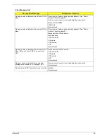
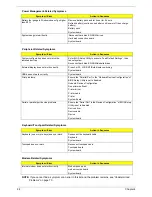
Indicator-Related Symptoms
Symptom / Error
Action in Sequence
Indicator incorrectly remains off or on, but system
runs correctly
Reconnect the inverter board
Inverter board
System board
Power-Related Symptoms
Symptom / Error
Action in Sequence
Power shuts down during operation
Power source (battery pack and power adapter). See “Power
System Check” on page 57.
Battery pack
Power adapter
Hard drive & battery connection board
System board
The system doesn’t power-on.
Power source (battery pack and power adapter). See “Power
System Check” on page 57.
Battery pack
Power adapter
Hard drive & battery connection board
System board
The system doesn’t power-off.
Power source (battery pack and power adapter). See “Power
System Check” on page 57.
Hold and press the power switch for more than 4 seconds.
System board
Summary of Contents for Aspire 5500Z Series
Page 6: ...VI ...
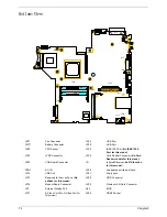
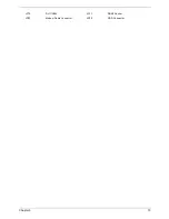
Page 14: ...6 Chapter 1 JP23 Modem Cable Connector JP39 ODD Connector ...
Page 36: ...28 Chapter 1 ...
Page 48: ...40 Chapter 2 ...
Page 57: ...Chapter 3 49 ...
Page 81: ...Chapter 5 73 JP19 RJ11 RJ45 JP31 DDR2 Socket JP23 Modem Cable Connector JP39 ODD Connector ...
Page 82: ...74 Chapter 5 ...
Page 84: ...76 Chapter 6 Exploded Diagram The System 011 012 013 ...
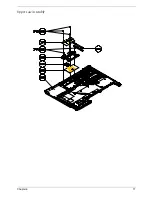
Page 85: ...Chapter 6 77 Upper Case Assembly ...
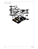
Page 86: ...78 Chapter 6 Lower Case Assembly ...
Page 87: ...Chapter 6 79 LCD Module ...
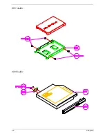
Page 88: ...80 Chapter 6 HDD Module ODD Module ...
Page 103: ...Index 104 ...

