68
Chapter 4
NOTE:
If you cannot find a symptom or an error in this list and the problem remains, see “Undetermined
Problems” on page 70.
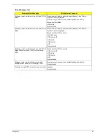
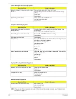
Battery fuel gauge in Windows doesn’t go higher
than 90%.
Remove battery pack and let it cool for 2 hours.
Refresh battery (continue use battery until power off, then charge
battery).
Battery pack
System board
System hangs intermittently.
Reconnect hard disk/CD-ROM drives.
Hard disk connection board
System board
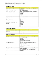
Peripheral-Related Symptoms
Symptom / Error
Action in Sequence
System configuration does not match the
installed devices.
Enter BIOS Setup Utility to execute “Load Default Settings”, then
reboot system.
Reconnect hard disk/CD-ROM/diskette drives.
External display does not work correctly.
Press Fn+F5, LCD/CRT/Both display switching
System board
USB does not work correctly
System board
Print problems.
Ensure the “Parallel Port” in the “Onboard Devices Configuration” of
BIOS Setup Utility is set to Enabled.
Onboard Devices Configuration
Run printer self-test.
Printer driver
Printer cable
Printer
System Board
Serial or parallel port device problems.
Ensure the “Serial Port” in the Devices Configuration” of BIOS Setup
Utility is set to Enabled.
Device driver
Device cable
Device
System board
Keyboard/Touchpad-Related Symptoms
Symptom / Error
Action in Sequence
Keyboard (one or more keys) does not work.
Reconnect the keyboard cable.
Keyboard
System board
Touchpad does not work.
Reconnect touchpad cable.
Touchpad board
System board
Modem-Related Symptoms
Symptom / Error
Action in Sequence
Internal modem does not work correctly.
Modem phone port
modem combo board
System board
Power Management-Related Symptoms
Symptom / Error
Action in Sequence
Summary of Contents for Aspire 5500Z Series
Page 6: ...VI ...
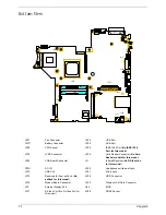
Page 14: ...6 Chapter 1 JP23 Modem Cable Connector JP39 ODD Connector ...
Page 36: ...28 Chapter 1 ...
Page 48: ...40 Chapter 2 ...
Page 57: ...Chapter 3 49 ...
Page 81: ...Chapter 5 73 JP19 RJ11 RJ45 JP31 DDR2 Socket JP23 Modem Cable Connector JP39 ODD Connector ...
Page 82: ...74 Chapter 5 ...
Page 84: ...76 Chapter 6 Exploded Diagram The System 011 012 013 ...
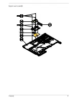
Page 85: ...Chapter 6 77 Upper Case Assembly ...
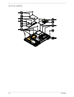
Page 86: ...78 Chapter 6 Lower Case Assembly ...
Page 87: ...Chapter 6 79 LCD Module ...
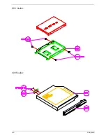
Page 88: ...80 Chapter 6 HDD Module ODD Module ...
Page 103: ...Index 104 ...

