47
Chapter 3
6.
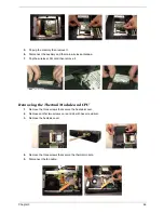
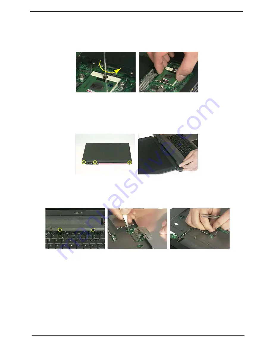
Use a flat-bladed screwdriver to release the CPU lock.
7.
Remove the CPU from the socket carefully.
Removing the LCD Module
1.
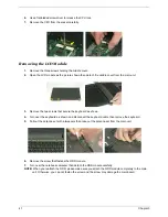
Remove the three screws holding the middle cover.
2.
Open the LCD module as the picture shown then detach the middle cover from the main unit.
.
3.
Remove the two screws that secure the keyboard as shown.
4.
Turn over the keyboard as shown and disconnect the keyboard cable then remove the keyboard.
5.
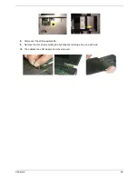
Pull out the antenna set with a tweezers then take out the antenna set from the main unit.
.
6.
Remove the screw that fastens the ODD module.
7.
Turn over the notebook computer then detach the ODD module carefully.
NOTE:
When you reattach the ODD, please make sure you attach the ODD module completely to the main
unit. Otherwise, you can not fasten the screw and the screw may damage the main board.
Summary of Contents for Aspire 5510
Page 84: ...Chapter 5 78 Top View Jumper and Connector Locations Chapter 5 ...
Page 85: ...79 Chapter 5 Rear View ...
Page 87: ...81 Chapter 5 RTC Jumper ...
Page 89: ...83 Chapter 6 Exploded Diagram ...
Page 105: ...99 Chapter 6 ...

