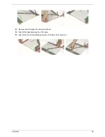
53
Chapter 3
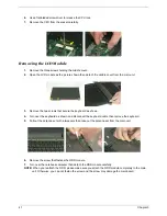
Disassembling the LCD Module
1.
Remove the four screw caps as shown.
2.
Remove the four screws holding the LCD bezel.
3.
Then detach the LCD bezel from the LCD module.
4.
Disconnect the inverter board then remove it.
5.
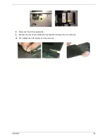
Remove the three screws holding the right hinge.
6.
Then remove the three screws that secure the left hinge.
7.
Remove one screw that secure the LCD bracket.
8.
Remove another screw holding the LCD bracket on the other side.
9.
Then detach the LCD panel from the LCD cover carefully.
.
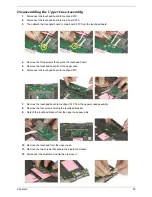
10.
Remove the two screws holding the right bracket.
11.
Then remove the right bracket.
12.
Remove another two screws that tighten the left bracket.
Summary of Contents for Aspire 5510
Page 84: ...Chapter 5 78 Top View Jumper and Connector Locations Chapter 5 ...
Page 85: ...79 Chapter 5 Rear View ...
Page 87: ...81 Chapter 5 RTC Jumper ...
Page 89: ...83 Chapter 6 Exploded Diagram ...
Page 105: ...99 Chapter 6 ...

