22
Chapter 2
Information
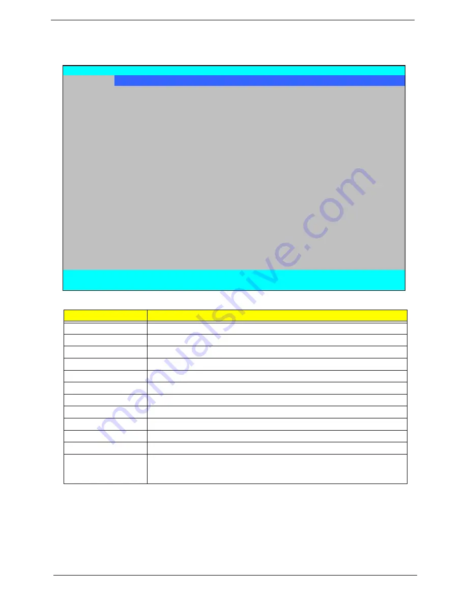
The Information screen displays a summary of your computer hardware information.
NOTE:
The system information is subject to different models.
Parameter
Description
CPU Type
This field shows the CPU type and speed of the system.
CPU Speed
This field shows the speed of the CPU.
IDE0 Model Name
This field shows the model name of HDD installed on primary IDE master.
IDE0 Serial Number
This field displays the serial number of HDD installed on primary IDE master.
ATAPI Model Name
This field shows the model name of the Optical device installed in the system.
System BIOS Version
Displays system BIOS version.
VGA BIOS Version
This field displays the VGA firmware version of the system.
Serial Number
This field displays the serial number of this unit.
Asset Tag Number
This field displays the asset tag number of the system.
Product Name
This field shows product name of the system.
Manufacturer Name
This field displays the manufacturer of this system.
UUID Number
Universally Unique Identifier (UUID) is an identifier standard used in software
construction, standardized by the Open Software Foundation (OSF) as part of
the Distributed Computing Environment (DCE).
Information
Main Advanced
Security
Power
Boot
Exit
CPU Type:
AMD Athlon(tm) Processor 2650e
CPU Speed:
1600 MHz
IDE0 Model Name:
W DC W D1600BEVT-22ZCT0 -(PM)
IDE0 Serial Number:
W D-W XE708J87380
ATAPI Model Name:
HL-DT-STDVDRAM GT10N -(PS)
System BIOS Version:
V0.08
VGA BIOS Version:
V010.055.000.049.029773
Serial Number:
S2N250Y001832099561601
Asset Tag Number:
Product Name:
Aspire..5515
Manufacturer Name:
Aspire
UUID:
39323232393932643635001EEC5A9BCF
F1
Help
↑↓
Select Item
F5/F6
Change Values
F9
Setup Defaults
Esc
Exit
←→
Select Menu
Enter
Select
X
Sub-Menu
F10
Save and Exit
PhoenixBIOS Setup Utility
Summary of Contents for Aspire 5515
Page 6: ...VI ...
Page 10: ...X Table of Contents ...
Page 31: ...Chapter 1 21 ...
Page 51: ...40 Chapter 2 ...
Page 56: ...Chapter 3 45 3 Carefully open the memory cover 4 Remove the HDD cover as shown ...
Page 59: ...48 Chapter 3 7 Press down on the locking catch to release the ODD cover and remove ...
Page 74: ...Chapter 3 63 8 Carefully remove the LCD module from the chassis ...
Page 104: ...Chapter 3 93 18 Reconnect the left side of the spring as shown ...
Page 107: ...96 Chapter 3 2 Replace the four screws and the rubber screw caps provided ...
Page 112: ...Chapter 3 101 7 Replace the six securing screws in the mainboard ...
Page 115: ...104 Chapter 3 ...
Page 129: ...118 Chapter 3 ...
Page 155: ...144 Chapter 5 ...
Page 175: ...164 Appendix C ...


