Chapter 3
109
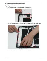
Replacing the Camera Board
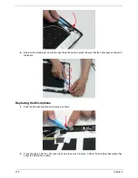
1.
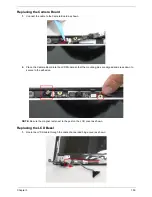
Connect the cable to the Camera Board as shown.
2.
Place the Camera Board into the LCD Module so that the mounting pins are aligned and press down to
secure to the adhesive.
NOTE:
Be sure the magnet rests next to the post on the LCD cover as shown.
Replacing the LCD Bezel
1.
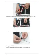
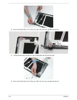
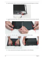
Route the LVDS cable through the cable channel and hinge cover as shown.
Summary of Contents for Aspire 5534 Series
Page 6: ...VI ...
Page 10: ...X Table of Contents ...
Page 32: ...22 Chapter 1 ...
Page 51: ...Chapter 2 41 ...
Page 52: ...42 Chapter 2 ...
Page 65: ...Chapter 3 55 ...
Page 79: ...Chapter 3 69 ...
Page 81: ...Chapter 3 71 5 Lift the Power Board from the Lower Cover ...
Page 83: ...Chapter 3 73 6 Lift the right side speaker out from the Lower Cover as shown ...
Page 89: ...Chapter 3 79 7 Disconnect the I O Board Cable from the I O Board ...
Page 97: ...Chapter 3 87 ...
Page 103: ...Chapter 3 93 ...
Page 107: ...Chapter 3 97 6 Disconnect the LCD cable as shown and remove the cable from the LCD Panel ...
Page 110: ...100 Chapter 3 ...
Page 197: ...Chapter 6 187 ...
Page 224: ...214 ...

