114
Chapter 3
2.
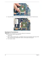
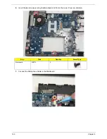
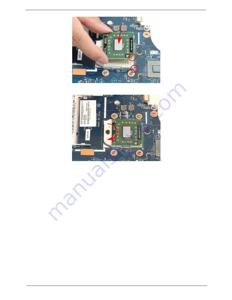
Using a flat blade screw driver, rotate the CPU screw 180° clockwise to lock the CPU into the socket.
Replacing the Thermal Module
IMPORTANT:
Ensure all heat pads are in place before replacing the Thermal Module.
The following thermal pads are approved for use:
•
Eapus XR-PE
1.
Remove all traces of thermal grease or pad adhesive from the CPU and thermal module using a lint-free
cloth or cotton swab and Isopropyl Alcohol, Acetone, or other approved cleaning agent.
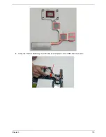
2.
Place the pads as shown.
Summary of Contents for Aspire 5534 Series
Page 6: ...VI ...
Page 10: ...X Table of Contents ...
Page 32: ...22 Chapter 1 ...
Page 51: ...Chapter 2 41 ...
Page 52: ...42 Chapter 2 ...
Page 65: ...Chapter 3 55 ...
Page 79: ...Chapter 3 69 ...
Page 81: ...Chapter 3 71 5 Lift the Power Board from the Lower Cover ...
Page 83: ...Chapter 3 73 6 Lift the right side speaker out from the Lower Cover as shown ...
Page 89: ...Chapter 3 79 7 Disconnect the I O Board Cable from the I O Board ...
Page 97: ...Chapter 3 87 ...
Page 103: ...Chapter 3 93 ...
Page 107: ...Chapter 3 97 6 Disconnect the LCD cable as shown and remove the cable from the LCD Panel ...
Page 110: ...100 Chapter 3 ...
Page 197: ...Chapter 6 187 ...
Page 224: ...214 ...


