Chapter 1
7
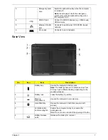
Base View
3
Emergency eject
hole
Ejects the optical drive tray when the computer
is turned off.
Note:
Insert a paper clip to the emergency
eject hole to eject the optical drive tray when
the computer is off.
4
USB 2.0 port
Connect to USB 2.0 devices (e.g., USB mouse,
USB camera).
5
Ethernet (RJ-45)
port
Connects to an Ethernet 10/100/1000- based
network.
6
DC-in jack
Connects to an AC adapter.
No.
Icon
Item
Description
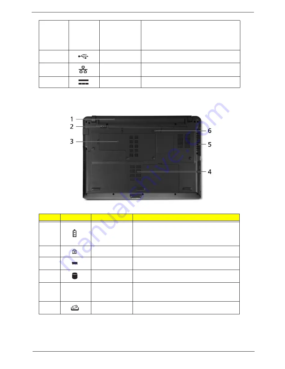
1
Battery bay
Houses the computer's battery pack.
Note:
The battery shown is for reference only. Your
PC may have a different battery, depending on the
model purchased.
2
Battery lock
Locks the battery in position.
3
Memory
compartment
Houses the computer's main memory.
4
Hard Disk Bay
Houses the computer's hard disk (secured with
screws).
5
Ventilation slots
and/or cooling fan
Enable the computer to stay cool, even after
prolonged use.
Note: Do not cover or obstruct the opening of the fan.
6
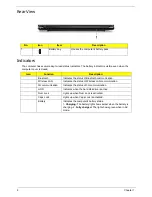
Battery Release
Latch
Releases the battery for removal.
Summary of Contents for Aspire 5534 Series
Page 6: ...VI ...
Page 10: ...X Table of Contents ...
Page 32: ...22 Chapter 1 ...
Page 51: ...Chapter 2 41 ...
Page 52: ...42 Chapter 2 ...
Page 65: ...Chapter 3 55 ...
Page 79: ...Chapter 3 69 ...
Page 81: ...Chapter 3 71 5 Lift the Power Board from the Lower Cover ...
Page 83: ...Chapter 3 73 6 Lift the right side speaker out from the Lower Cover as shown ...
Page 89: ...Chapter 3 79 7 Disconnect the I O Board Cable from the I O Board ...
Page 97: ...Chapter 3 87 ...
Page 103: ...Chapter 3 93 ...
Page 107: ...Chapter 3 97 6 Disconnect the LCD cable as shown and remove the cable from the LCD Panel ...
Page 110: ...100 Chapter 3 ...
Page 197: ...Chapter 6 187 ...
Page 224: ...214 ...

