174
Chapter 5
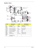
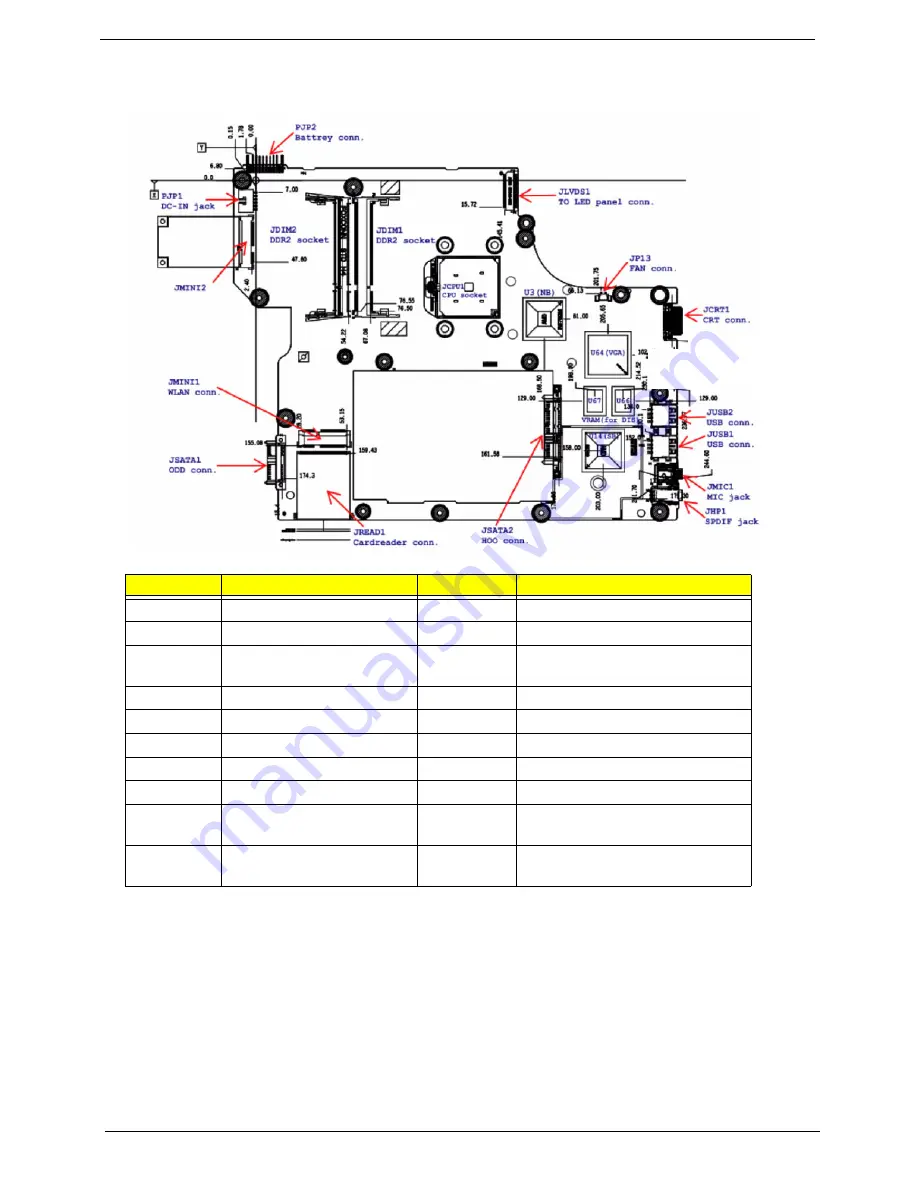
Bottom View
ITEM
DESCRIPTION
ITEM
DESCRIPTION
PJP1
Connect to Battery
JHP1
Connect to external SPDIF
PJP2
DC-IN jack
JREAD1
Card reader
JDIM1 /
JDIM2
DDR2 Memory socket
JCRT1
CRT Connector
JLVDS1
Connect to LED Panel
JP13
FAN Connector
JSATA1
Connect to SATA ODD
JCPU1
CPU socket
JSATA2
Connect to SATA HDD
U3
NB
JMINI1
Connect to WLAN
U14
SB
JMINI2
Reserved
U64
M92-S2LP VGA
JUSB1 /
JUSB2
USB Connector
U66 / U67
VRAM (for DIS)
JMIC1
Connect to external
microphone
Summary of Contents for Aspire 5534 Series
Page 6: ...VI ...
Page 10: ...X Table of Contents ...
Page 32: ...22 Chapter 1 ...
Page 51: ...Chapter 2 41 ...
Page 52: ...42 Chapter 2 ...
Page 65: ...Chapter 3 55 ...
Page 79: ...Chapter 3 69 ...
Page 81: ...Chapter 3 71 5 Lift the Power Board from the Lower Cover ...
Page 83: ...Chapter 3 73 6 Lift the right side speaker out from the Lower Cover as shown ...
Page 89: ...Chapter 3 79 7 Disconnect the I O Board Cable from the I O Board ...
Page 97: ...Chapter 3 87 ...
Page 103: ...Chapter 3 93 ...
Page 107: ...Chapter 3 97 6 Disconnect the LCD cable as shown and remove the cable from the LCD Panel ...
Page 110: ...100 Chapter 3 ...
Page 197: ...Chapter 6 187 ...
Page 224: ...214 ...

