Chapter 5
175
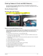
Clearing Password Check and BIOS Recovery
This section provide you the standard operating procedures of clearing password and BIOS recovery for
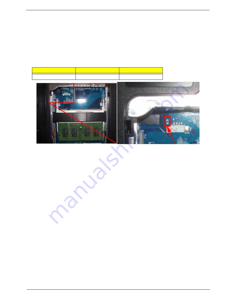
Aspire 5534. Aspire 5534 provides one Hardware Open Gap on main board for clearing password check, and
one Hotkey for enabling BIOS Recovery.
Clearing Password Check
Hardware Open Gap Description
Steps for Clearing BIOS Password Check
If users set BIOS Password (Supervisor Password and/or User Password) for a security reason, BIOS will ask
the password during systems POST or when systems enter to BIOS Setup menu. However, once it is
necessary to bypass the password check, users need to short the HW Gap to clear the password by the
following steps:
1.
Flash to BIOS v1.04 (or later version), and enter BIOS Setup Utility.
2.
Set the Supervisor password, User Password, and power on password. Press
F10
, and save and exit.
After the Save, the notebook auto re-starts.
3.
After power-on, the system prompts to input the password. Enter the password set in step 1 and allow the
device to startup.
4.
Press and hold the power key to shutdown the system.
5.
Open the memory door and remove the memory modules.
6.
Remove the battery pack and AC adapter.
7.
Short the R72 Pins shown above (ensure that the circuit is complete).
8.
Replace the memory modules and close memory door.
9.
Replace the battery pack and power on the system.
10.
Press
F2
at the prompt to enter BIOS. Check the
Security
screen shows Supervisor and User
Passwords are clear.
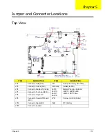
Item
Description
Location
R397
Clear CMOS Jumper
Memory Bay
Summary of Contents for Aspire 5534 Series
Page 6: ...VI ...
Page 10: ...X Table of Contents ...
Page 32: ...22 Chapter 1 ...
Page 51: ...Chapter 2 41 ...
Page 52: ...42 Chapter 2 ...
Page 65: ...Chapter 3 55 ...
Page 79: ...Chapter 3 69 ...
Page 81: ...Chapter 3 71 5 Lift the Power Board from the Lower Cover ...
Page 83: ...Chapter 3 73 6 Lift the right side speaker out from the Lower Cover as shown ...
Page 89: ...Chapter 3 79 7 Disconnect the I O Board Cable from the I O Board ...
Page 97: ...Chapter 3 87 ...
Page 103: ...Chapter 3 93 ...
Page 107: ...Chapter 3 97 6 Disconnect the LCD cable as shown and remove the cable from the LCD Panel ...
Page 110: ...100 Chapter 3 ...
Page 197: ...Chapter 6 187 ...
Page 224: ...214 ...


