212
Internal Microphone Failure
155
Internal Power Cable
80
Internal Speaker Failure
153
J
Jumper and Connector Locations
173
Top View
173
K
Keyboard
Removing
60
Replacing
136
Keyboard Failure
152
L
LCD Bezel
Removing
91
Replacing
109
LCD Brackets
Removing
98
Replacing
105
LCD Cable
Removing
96
,
107
LCD Failure
152
LCD Module
Disassembly
90
Reassembly
103
Removing
84
Replacing
112
LCD Module Disassembly
Flowchart
90
LCD Panel
Removing
95
Replacing
108
Lower Covers
Replacing
145
M
Main Unit Disassembly
Flowchart
58
Mainboard
Removing
81
Replacing
118
media access
on indicator
8
Media Board
Removing
74
Replacing
124
Microphone
Removing
99
Replacing
104
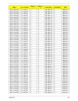
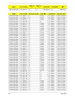
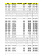
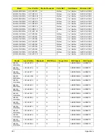
Model Definition
188
N
No Display Issue
150
num lock
on indicator
8
O
ODD
Replacing
143
Online Support Information
210
optical drive module
49
P
Panel
4
left
4
PC Card
8
Power Board
Removing
70
Replacing
127
S
Speaker Module
Replacing
125
Speaker Modules
Removing
72
speakers
hotkey
12
System
Block Diagram
3
T
Test Compatible Components
206
Thermal Module
Removing
88
Replacing
114
Thermal Unit Failure
163
Top
173
Touchpad Bracket
Removing
68
Replacing
128
Summary of Contents for Aspire 5534 Series
Page 6: ...VI ...
Page 10: ...X Table of Contents ...
Page 32: ...22 Chapter 1 ...
Page 51: ...Chapter 2 41 ...
Page 52: ...42 Chapter 2 ...
Page 65: ...Chapter 3 55 ...
Page 79: ...Chapter 3 69 ...
Page 81: ...Chapter 3 71 5 Lift the Power Board from the Lower Cover ...
Page 83: ...Chapter 3 73 6 Lift the right side speaker out from the Lower Cover as shown ...
Page 89: ...Chapter 3 79 7 Disconnect the I O Board Cable from the I O Board ...
Page 97: ...Chapter 3 87 ...
Page 103: ...Chapter 3 93 ...
Page 107: ...Chapter 3 97 6 Disconnect the LCD cable as shown and remove the cable from the LCD Panel ...
Page 110: ...100 Chapter 3 ...
Page 197: ...Chapter 6 187 ...
Page 224: ...214 ...

