Chapter 1
15
System Memory
Video Specifications
Hard Disk Drive Interface
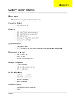
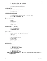
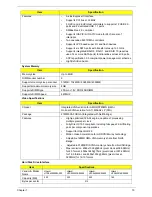
Features
•
A-Link Express II interface
•
Supports PCI bus at 33 MHz
•
5 OHCI and 2 EHCI Host controllers to supports 12 USB 2.0
ports and 2 dedicated USB 1.1 ports
•
SMBus Rev. 2.0 compliant
•
Supports IOAPIC/X-IO APIC mode for 24 channels of
interrupts
•
Two cascaded 8237 DMA controllers
•
Supports LPC based super I/O and flash devices
•
Supports six SATA ports with transfer rates up to 3 Gb/s
•
Supports integrated RAID 0, RAID 1, and RAID 10 (requires
use of 4 or more SATA ports) functionalities across all 6 ports.
•
ACPI specification 3.0 compliant power management schemes
•
High Definition Audio
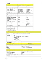
Item
Specification
Memory size
Up to 8GB
DIMM socket number
2
Supports memory size per socket
512MB / 1024MB / 2048MB / 4096MB
Supports maximum memory size
8GB
Supports DIMM type
200-pin +1.8V DDRII SODIMM
Supports DIMM Speed
667MHZ
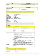
Item
Specification
Chipset
Integrated VGA solution for AMD RS780MN (UMA).
On board VGA solution for ATI M92-S2 LP (DIS).
Package
21MM 528-FCBGA (Integrated with Northbridge)
Features
•
Highly-optimized 128-bit engine, capable of processing
multiple pixels per clock.
•
Fully DirectX 10.0 compliant, including full speed 32-bit floating
point per component operations
•
Support for OpenGL® 2.0
•
Motion Video Acceleration for HD DVD/Blu-ray technology
•
Adjustable 128MB UMA VGA memory share from North
Bridge.
•
Adjustable 512MB DIS VGA memory share from North Bridge.
•
Max resoluiton 2048x1536 @85Hz (pixel clock at 388.5MHz)
for 4:3 format, 2560x1440 @75Hz (pixel clock at 397.25MHz)
for 16:9 format, and 2456x1536 @60Hz (pixel clock at
320MHz) for 16:10 format
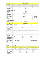
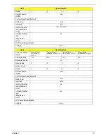
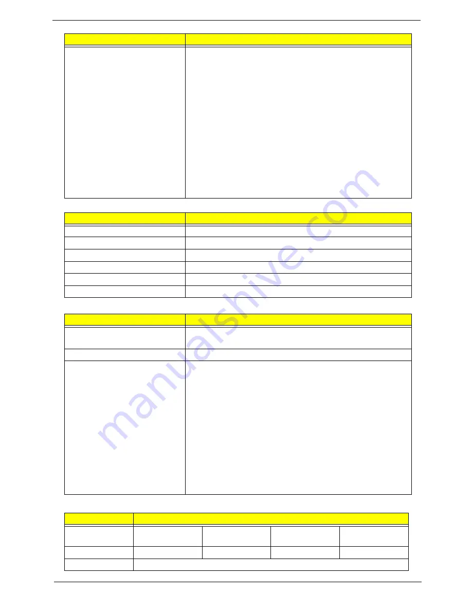
Item
Specifications
Vendor & Model
Name
Hitachi
HTS545050B9A300
Hitachi
HTS545032B9A300
Hitachi
HTS545025B9A300
Hitachi
HTS545016B9A300
Capacity (MB)
500
320
250
160
Bytes per sector
512
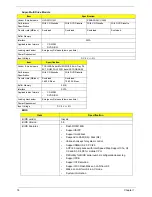
Item
Specification
Summary of Contents for Aspire 5534 Series
Page 6: ...VI ...
Page 10: ...X Table of Contents ...
Page 32: ...22 Chapter 1 ...
Page 51: ...Chapter 2 41 ...
Page 52: ...42 Chapter 2 ...
Page 65: ...Chapter 3 55 ...
Page 79: ...Chapter 3 69 ...
Page 81: ...Chapter 3 71 5 Lift the Power Board from the Lower Cover ...
Page 83: ...Chapter 3 73 6 Lift the right side speaker out from the Lower Cover as shown ...
Page 89: ...Chapter 3 79 7 Disconnect the I O Board Cable from the I O Board ...
Page 97: ...Chapter 3 87 ...
Page 103: ...Chapter 3 93 ...
Page 107: ...Chapter 3 97 6 Disconnect the LCD cable as shown and remove the cable from the LCD Panel ...
Page 110: ...100 Chapter 3 ...
Page 197: ...Chapter 6 187 ...
Page 224: ...214 ...

