Chapter 3
53
11.
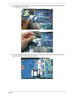
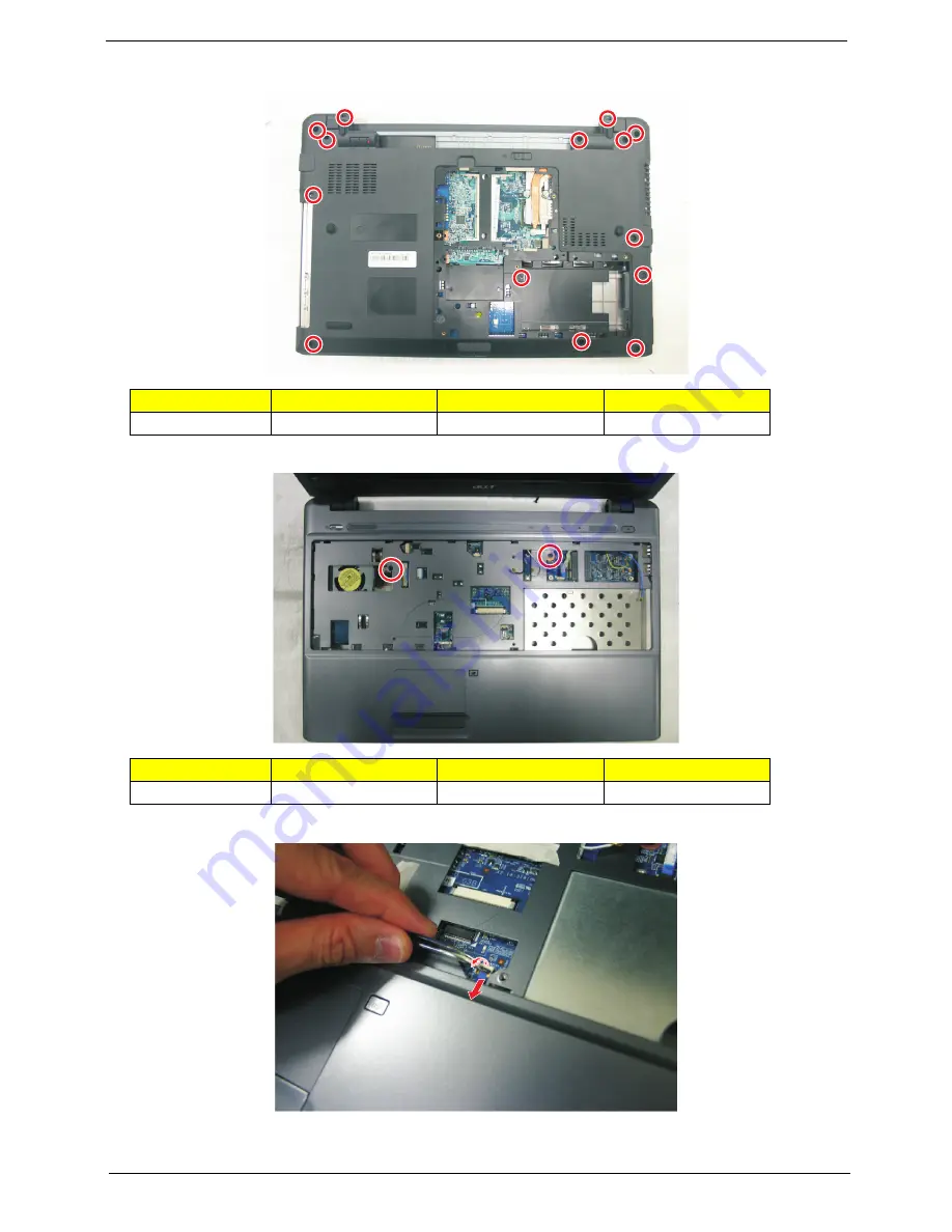
Remove the fourteen screws (A) from the bottom panel.
12.
Turn over the unit and remove the two screws (A) on the top panel.
13.
Disconnect the touchpad cable from the TPAD1 connector on the main board.
Step
Size (Quantity)
Color
Torque
1~14
M2.5 x L6 (14)
Black
3.0 kgf-cm
Step
Size (Quantity)
Color
Torque
1~2
M2.5 x L6 (2)
Black
3.0 kgf-cm
Summary of Contents for Aspire 5810T Series
Page 6: ...VI...
Page 11: ...Chapter 1 3 Aspire 5810T 5810TZ 5410T System Block Diagram...
Page 12: ...4 Chapter 1 Aspire 5810TG System Block Diagram...
Page 17: ...Chapter 1 9 Rear View Icon Item Description 1 Battery bay Houses the computer s battery pack...
Page 46: ...38 Chapter 2...
Page 108: ...108 Chapter 6 Aspire 5810T 5810TZ 5410T Series Exploded Diagram...
Page 109: ...Chapter 6 109 Aspire 5810TG Series Exploded Diagram...
Page 131: ...Appendix A 117 Model Definition and Configuration Appendix A...
Page 142: ...Appendix A 128...
Page 146: ...132 Appendix B...
Page 148: ...134 Appendix C...
Page 152: ...138...


