140
Chapter 4
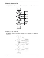
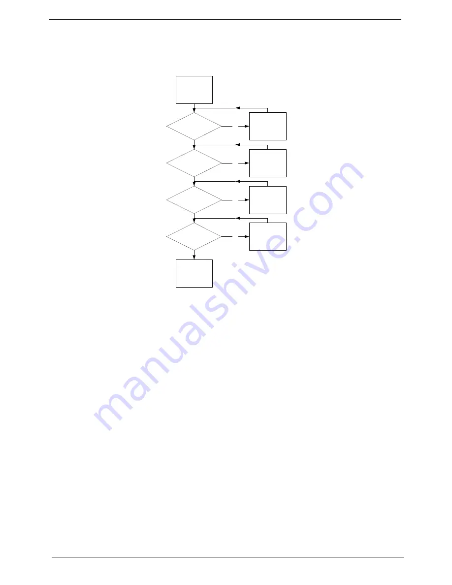
Thermal Unit Failure
If the
Thermal
Unit
fails, perform the following actions one at a time to correct the problem. Do not replace a
non-defective FRUs:
External Mouse Failure
If an external
Mouse
fails, perform the following actions one at a time to correct the problem.
1.
Try an alternative mouse.
2.
If the mouse uses a wireless connection, insert new batteries and confirm there is a good connection. See
the mouse user manual.
3.
If the mouse uses a USB connection, try an alternate USB port.
4.
Try an alternative program to verify mouse operation. Reinstall the program experiencing mouse failure.
5.
Restart the computer.
6.
Remove any recently added hardware and associated software.
7.
Remove any recently added software and reboot.
8.
Restore system and file settings from a known good date using
System
Restore
.
If the issue is not fixed, repeat the preceding steps and select an earlier time and date.
9.
Run the Event Viewer to check the events log for errors. For more information see Windows Help and
Support.
10.
Roll back the mouse driver to the previous version if updated recently.
11.
Remove and reinstall the mouse driver.
12.
Check the Device Manager to determine that:
•
The device is properly installed. There are no red Xs or yellow exclamation marks.
•
There are no device conflicts.
START
Fan cable well
connected?
Fan OK?
CPU heat sink
well seated?
CPU OK?
Replace
Mainboard
Connect it well
Seat it well
Replace CPU
Replace fan
No
No
No
No
Summary of Contents for Aspire 5935 Series
Page 6: ...VI ...
Page 10: ...X Table of Contents ...
Page 14: ...4 Chapter 1 System Block Diagram ...
Page 47: ...Chapter 2 37 ...
Page 54: ...44 Chapter 2 ...
Page 83: ...Chapter 3 73 5 Disconnect the cable from the Power Saving Board as shown ...
Page 88: ...78 Chapter 3 8 Remove the FInger Print Reader from the bracket as shown ...
Page 98: ...88 Chapter 3 4 Lift the right side Saddle clear of the Lower Cover as shown ...
Page 102: ...92 Chapter 3 5 Disconnect the cable from the Bluetooth Module ...
Page 109: ...Chapter 3 99 5 Using both hands lift the Thermal Module clear of the Mainboard ...
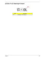
Page 161: ...Chapter 5 151 LS 5011P LCD Backlight Board Item Description JP1 Backlight on off Connector ...
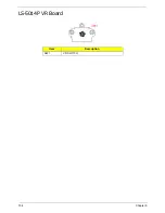
Page 164: ...154 Chapter 5 LS 5014P VR Board Item Description SW1 VR SWITCH ...
Page 165: ...Chapter 5 155 LS 5015P Finger printer Board Item Description U2 LTT SS801U 13_LGA28 ...
Page 170: ...160 Chapter 5 LS 501AP HDMI Board Item Description U1 CH7318A BF TR_QFN48_7X7 ...
Page 183: ...Chapter 6 173 ...
Page 212: ...Appendix A 202 ...
Page 218: ...208 Appendix B ...
Page 220: ...210 Appendix C ...
Page 224: ...214 ...


