146
Chapter 4
51h
Initialize EISA board
52h
Test keyboard
54h
Set key click if enabled
58h
2-2-3-1
Test for unexpected interrupts
59h
Initialize POST display service
5Ah
Display prompt
Press F2 to enter SETUP
5Bh
Disable CPU cache
5Ch
Test RAM between 512 and 640 KB
60h
Test extended memory
62h
Test extended memory address lines
64h
Jump to UserPatch1
66h
Configure advanced cache registers
67h
Initialize Multi Processor APIC
68h
Enable external and CPU caches
69h
Setup System Management Mode (SMM) area
6Ah
Display external L2 cache size
6Bh
Load custom defaults (optional)
6Ch
Display shadow-area message
6Eh
Display possible high address for UMB recovery
70h
Display error messages
72h
Check for configuration errors
76h
Check for keyboard errors
7Ch
Set up hardware interrupt vectors
7Eh
Initialize coprocessor if present
80h
Disable onboard Super I/O ports and IRQs
81h
Late POST device initialization
82h
Detect and install external RS232 ports
83h
Configure non-MCD IDE controllers
84h
Detect and install external parallel ports
85h
Initialize PC-compatible PnP ISA devices
86h
Re-initialize onboard I/O ports.
87h
Configure Motherboard Configurable Devices (optional)
88h
Initialize BIOS Data Area
89h
Enable Non-Maskable Interrupts (NMIs)
8Ah
Initialize Extended BIOS Data Area
8Bh
Test and initialize PS/2 mouse
8Ch
Initialize floppy controller
8Fh
Determine number of ATA drives (optional)
90h
Initialize hard-disk controllers
91h
Initialize local-bus hard-disk controllers
92h
Jump to UserPatch2
93h
Build MPTABLE for multi-processor boards
95h
Install CD ROM for boot
Code
Beeps
POST Routine Description
Summary of Contents for Aspire 5935 Series
Page 6: ...VI ...
Page 10: ...X Table of Contents ...
Page 14: ...4 Chapter 1 System Block Diagram ...
Page 47: ...Chapter 2 37 ...
Page 54: ...44 Chapter 2 ...
Page 83: ...Chapter 3 73 5 Disconnect the cable from the Power Saving Board as shown ...
Page 88: ...78 Chapter 3 8 Remove the FInger Print Reader from the bracket as shown ...
Page 98: ...88 Chapter 3 4 Lift the right side Saddle clear of the Lower Cover as shown ...
Page 102: ...92 Chapter 3 5 Disconnect the cable from the Bluetooth Module ...
Page 109: ...Chapter 3 99 5 Using both hands lift the Thermal Module clear of the Mainboard ...
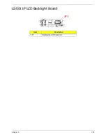
Page 161: ...Chapter 5 151 LS 5011P LCD Backlight Board Item Description JP1 Backlight on off Connector ...
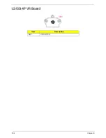
Page 164: ...154 Chapter 5 LS 5014P VR Board Item Description SW1 VR SWITCH ...
Page 165: ...Chapter 5 155 LS 5015P Finger printer Board Item Description U2 LTT SS801U 13_LGA28 ...
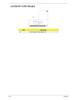
Page 170: ...160 Chapter 5 LS 501AP HDMI Board Item Description U1 CH7318A BF TR_QFN48_7X7 ...
Page 183: ...Chapter 6 173 ...
Page 212: ...Appendix A 202 ...
Page 218: ...208 Appendix B ...
Page 220: ...210 Appendix C ...
Page 224: ...214 ...

