162
Chapter 5
BIOS Recovery by Crisis Disk
BIOS Recovery Boot Block:
BIOS Recovery Boot Block is a special block of BIOS. It is used to boot up the system with minimum BIOS
initialization. Users can enable this feature to restore the BIOS firmware to a successful one once the previous
BIOS flashing process failed.
BIOS Recovery Hotkey:
The system provides a function hotkey:
Fn+Esc
, for enable BIOS Recovery process when system is powered
on during BIOS POST. To use this function, it is strongly recommended to have the AC adapter and Battery
present. If this function is enabled, the system will force the BIOS to enter a special BIOS block, called Boot
Block.
Steps for BIOS Recovery by Crisis Disk:
Before doing this, a Crisis Diskette should be prepared ready in hand. The Crisis Diskette could be made by
executing the Crisis Disk program in another system with Windows XP OS.
Follow the steps below:
1.
Plug in the USB disk.
2.
Launch the
wincris.exe
program to create a USB Crisis Disk. Click
Start
to initiate the process.
3.
Select the
Quick Format
option to format the disk and click
Start
. Follow the instructions on the screen to
create the disk.
4.
Copy the
KAYF0X64.fd
BIOS file into USB flash disk root directory.
NOTE:
Do not place any other *.fd file in the USB flash disk root directory.
To use the Crisis USB key, do the following:
1.
Plug USB storage into USB port.
2.
Press
Fn + ESC
button then plug in AC power.
The Power button flashes orange once.
3.
Press
Power
button to initiate system CRISIS mode.
When CRISIS is complete, the system auto restarts with a workable BIOS.
4.
Update the latest version BIOS for this machine by regular BIOS flashing process.
Summary of Contents for Aspire 5935 Series
Page 6: ...VI ...
Page 10: ...X Table of Contents ...
Page 14: ...4 Chapter 1 System Block Diagram ...
Page 47: ...Chapter 2 37 ...
Page 54: ...44 Chapter 2 ...
Page 83: ...Chapter 3 73 5 Disconnect the cable from the Power Saving Board as shown ...
Page 88: ...78 Chapter 3 8 Remove the FInger Print Reader from the bracket as shown ...
Page 98: ...88 Chapter 3 4 Lift the right side Saddle clear of the Lower Cover as shown ...
Page 102: ...92 Chapter 3 5 Disconnect the cable from the Bluetooth Module ...
Page 109: ...Chapter 3 99 5 Using both hands lift the Thermal Module clear of the Mainboard ...
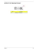
Page 161: ...Chapter 5 151 LS 5011P LCD Backlight Board Item Description JP1 Backlight on off Connector ...
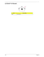
Page 164: ...154 Chapter 5 LS 5014P VR Board Item Description SW1 VR SWITCH ...
Page 165: ...Chapter 5 155 LS 5015P Finger printer Board Item Description U2 LTT SS801U 13_LGA28 ...
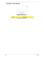
Page 170: ...160 Chapter 5 LS 501AP HDMI Board Item Description U1 CH7318A BF TR_QFN48_7X7 ...
Page 183: ...Chapter 6 173 ...
Page 212: ...Appendix A 202 ...
Page 218: ...208 Appendix B ...
Page 220: ...210 Appendix C ...
Page 224: ...214 ...

