175
Appendix A
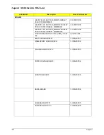
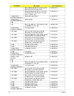
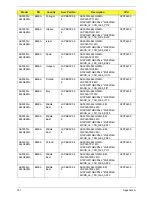
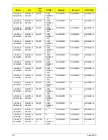
AS5935G-
644G32Mn
EMEA
France
LX.PBJ0X.006
AS5935G-644G32Mn
VHP32ATFR1 MC
M92XT512CFPbk 2*2G/320/BT/
8L/6R/
CB_n2_FP_1.0D_GEb_FR23
C2DT6400
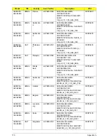
AS5935G-
863G32Mn
EMEA
Switzerlan
d
LX.PBJ0X.005
AS5935G-863G32Mn
VHP32ATCH1 MC
M92XT512CFPbk 2G+1G/320/BT/
6L/6R/
CB_n2_FP_1.0D_GEb_IT42
C2DP8600
AS5935G-
863G50Bn
EMEA
Switzerlan
d
LX.PBJ0X.003
AS5935G-863G50Bn
VHP32ATCH1 MC
M92XT512CFPbk 2G+1G/500_L/
BT/6L/6R/
CB_n2_FP_1.0D_GEb_IT42
C2DP8600
AS5935G-
864G50Mn
AAP
Philippine
s
LX.PBJ0U.001
AS5935G-864G50Mn
VUT32ATPH1 MC
M92XT512CFPbk 2*2G/500_L/
BT/8L/6R/
CB_n2_FP_1.0D_GEb_EN13
C2DP8600
AS5935G-
862G32Mn
AAP
Malaysia
LX.PBJ0X.002
AS5935G-862G32Mn EM
VHP32ATMY1 MC
M92XT512CFPbk 1*2G/320/BT/
8L/6R/
CB_n2_FP_1.0D_GEb_EN14
C2DP8600
AS5935G-
643G32Mn
EMEA
Middle
East
LX.PBJ0X.001
AS5935G-643G32Mn EM
VHP32ATME2 MC
M92XT512CFPbk 2G+1G/320/BT/
6L/6R/
CB_n2_FP_1.0D_GEb_AR23
C2DT6400
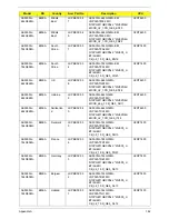
AS5935G-
644G32Mn
EMEA
Switzerlan
d
LX.PD80X.00
1
AS5935G-644G32Mn
VHP32ATCH1 MC
M92XT512CFbk 2*2G/320/BT/6L/
6R/CB_n2_FP_1.0D_GEb_IT42
C2DT6400
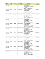
AS5935G-
643G25Mn
EMEA
Holland
LX.PB30X.008
AS5935G-643G25Mn
VHP32ATNL1 MC
M92XT512CPbk 2G+1G/250/6L/
6R/CB_n2_1.0D_GEb_NL12
C2DT6400
AS5935G-
643G25Mn
EMEA
Belgium
LX.PB30X.007
AS5935G-643G25Mn
VHP32ATBE1 MC
M92XT512CPbk 2G+1G/250/6L/
6R/CB_n2_1.0D_GEb_NL13
C2DT6400
AS5935G-
643G25Mn
EMEA
Luxembo
urg
LX.PB30X.006
AS5935G-643G25Mn
VHP32ATLU3 MC
M92XT512CPbk 2G+1G/250/6L/
6R/CB_n2_1.0D_GEb_IT41
C2DT6400
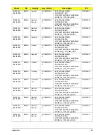
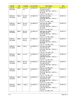
AS5935G-
744G32Mn
EMEA
Spain
LX.PB30X.005
AS5935G-744G32Mn
VHP32ATES1 MC
M92XT512CPbk 2*2G/320/BT/6L/
6R/CB_n2_1.0D_GEb_ES22
C2DP7450
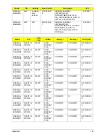
AS5935G-
743G32Mn
AAP
Singapore
LX.PB30X.001
AS5935G-743G32Mn
VHP32ATSG1 MC
M92XT512CPbk 2G+1G/320/BT/
8L/6R/CB_n3_1.0D_GEb_EN12
C2DP7450
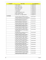
Model
RO
Country
Acer Part No
Description
CPU
Summary of Contents for Aspire 5935 Series
Page 6: ...VI ...
Page 10: ...X Table of Contents ...
Page 14: ...4 Chapter 1 System Block Diagram ...
Page 47: ...Chapter 2 37 ...
Page 54: ...44 Chapter 2 ...
Page 83: ...Chapter 3 73 5 Disconnect the cable from the Power Saving Board as shown ...
Page 88: ...78 Chapter 3 8 Remove the FInger Print Reader from the bracket as shown ...
Page 98: ...88 Chapter 3 4 Lift the right side Saddle clear of the Lower Cover as shown ...
Page 102: ...92 Chapter 3 5 Disconnect the cable from the Bluetooth Module ...
Page 109: ...Chapter 3 99 5 Using both hands lift the Thermal Module clear of the Mainboard ...
Page 161: ...Chapter 5 151 LS 5011P LCD Backlight Board Item Description JP1 Backlight on off Connector ...
Page 164: ...154 Chapter 5 LS 5014P VR Board Item Description SW1 VR SWITCH ...
Page 165: ...Chapter 5 155 LS 5015P Finger printer Board Item Description U2 LTT SS801U 13_LGA28 ...
Page 170: ...160 Chapter 5 LS 501AP HDMI Board Item Description U1 CH7318A BF TR_QFN48_7X7 ...
Page 183: ...Chapter 6 173 ...
Page 212: ...Appendix A 202 ...
Page 218: ...208 Appendix B ...
Page 220: ...210 Appendix C ...
Page 224: ...214 ...


