42
Chapter 2
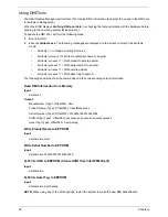
Using DMITools
The DMI (Desktop Management Interface) Tool copies BIOS information to eeprom to be used in the DMI pool
for hardware management.
When the BIOS displays
Verifying DMI pool data
it is checking the table correlates with the hardware before
sending to the operating system (Windows, etc.).
To update the DMI Pool, perform the following steps:
1.
Boot into DOS.
2.
Execute
dmitools.exe
. The following messages are displayed on the screen to prompt the dmitools
mode.
•
dmitools /r ==> Read dmi string from bios
•
dmitools /wm xxxx ==> Write manufacturer name to eeprom
•
dmitools /wp xxxx ==> Write product name to eeprom
•
dmitools /ws xxxx ==> Write serial number to eeprom
•
dmitools /wu xxxx ==> Write uuid to eeprom
•
dmitools /wa xxxx ==> Write asset tag to eeprom
The following examples show the commands and the corresponding output information.
Read DMI Information from Memory
Input:
dmitools /r
Output:
Manufacturer (Type1, Offset04h): Acer
Product Name (Type1, Offset05h): TravelMate xxxxx
Serial Number (Type1, Offset07h): 01234567890123456789
UUID String (Type1, Offset08h): xxxxxxxx-xxxx-xxxx-xxxx-xxxxxxxxxxxx
Asset Tag (Type3, Offset04h): Acet Asstag
Write Product Name to EEPROM
Input:
dmitools /wp Acer
Write Serial Number to EEPROM
Input:
dmitools /ws 01234567890123456789
4). Write UUID to EEPROM (Create UUID from Intel WFM20.pdf)
Input:
dmitools /wu
5). Write Asset Tag to EEPROM
Input:
dmitools /wa Acet Asstag
NOTE:
When using any of the Write options, restart the system to make the new DMI data effective.
Summary of Contents for Aspire 5935 Series
Page 6: ...VI ...
Page 10: ...X Table of Contents ...
Page 14: ...4 Chapter 1 System Block Diagram ...
Page 47: ...Chapter 2 37 ...
Page 54: ...44 Chapter 2 ...
Page 83: ...Chapter 3 73 5 Disconnect the cable from the Power Saving Board as shown ...
Page 88: ...78 Chapter 3 8 Remove the FInger Print Reader from the bracket as shown ...
Page 98: ...88 Chapter 3 4 Lift the right side Saddle clear of the Lower Cover as shown ...
Page 102: ...92 Chapter 3 5 Disconnect the cable from the Bluetooth Module ...
Page 109: ...Chapter 3 99 5 Using both hands lift the Thermal Module clear of the Mainboard ...
Page 161: ...Chapter 5 151 LS 5011P LCD Backlight Board Item Description JP1 Backlight on off Connector ...
Page 164: ...154 Chapter 5 LS 5014P VR Board Item Description SW1 VR SWITCH ...
Page 165: ...Chapter 5 155 LS 5015P Finger printer Board Item Description U2 LTT SS801U 13_LGA28 ...
Page 170: ...160 Chapter 5 LS 501AP HDMI Board Item Description U1 CH7318A BF TR_QFN48_7X7 ...
Page 183: ...Chapter 6 173 ...
Page 212: ...Appendix A 202 ...
Page 218: ...208 Appendix B ...
Page 220: ...210 Appendix C ...
Page 224: ...214 ...

