Chapter 3
63
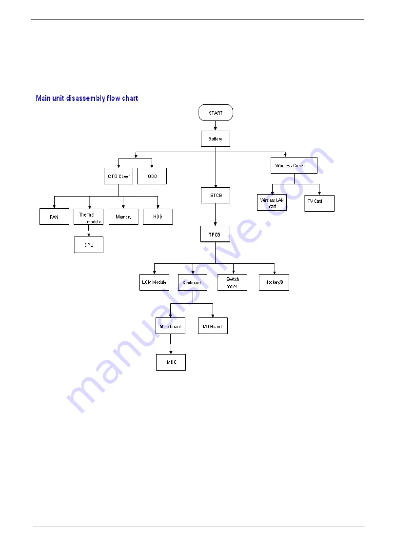
Disassembly Procedure Flowchart
The flowchart on the succeeding page gives you a graphic representation on the entire disassembly sequence
and instructs you on the components that need to be removed during servicing. For example, if you want to
remove the system board, you must first remove the keyboard, then disassemble the inside assembly frame in
that order.
Summary of Contents for Aspire 6920
Page 6: ...VI ...
Page 10: ...4 Chapter 1 System Block Diagram ...
Page 11: ...Chapter 1 5 Board Layout ...
Page 12: ...6 Chapter 1 ...
Page 14: ...8 Chapter 1 Closed Front View ...
Page 15: ...Chapter 1 9 Left View ...
Page 16: ...10 Chapter 1 Right View ...
Page 17: ...Chapter 1 11 ...
Page 18: ...12 Chapter 1 Base view ...
Page 30: ...24 Chapter 1 ...
Page 62: ...62 Chapter 2 Then the HDD password will be unlocked and will auto into Windows after reboot ...
Page 66: ...64 Chapter 3 ...
Page 97: ...Chapter 5 97 Jumper and Connector Locations Chapter 5 ...
Page 98: ...98 Chapter 5 Bottom View ...
Page 99: ...Chapter 5 99 ...
Page 100: ...100 Chapter 5 ...
Page 102: ...100 Chapter 6 Aspire6920 Exploded Diagram ...
Page 103: ...Chapter 6 101 ...
Page 104: ...102 Chapter 6 ...
Page 105: ...Chapter 6 103 ...


