4
Chapter 1
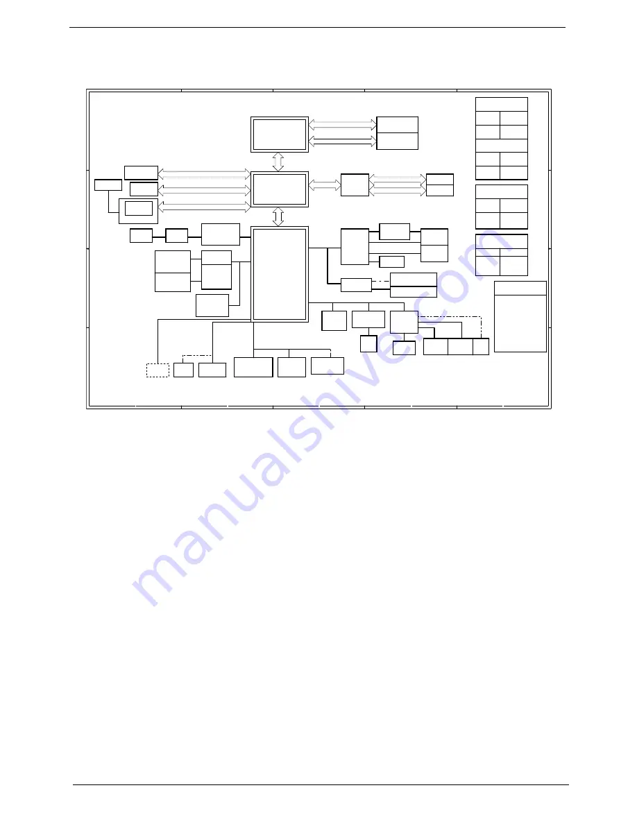
Block Diagram
A
A
B
B
C
C
D
D
E
E
4
4
3
3
2
2
1
1
-1
1
59
M A C
C51MV
5V_S5
18V 3.0A
5V 100mA
VCC_CORE_S0
CRT /TV
MUX
PCIE x 1
MYALL M Block Diagram
ATA 133
HD AUDIO
LPC I/F
HyperTransport
16X16
6.4GB/S
NPT Processor
Rev. F
S1 package
AMD CPU
DDRII
667
LCD
nVIDIA
MCP51
A CPI 2.0
Mini Card
802.11a/b/g
P CI
8xUSB 2.0
nVIDIA
HyperTr UMA
HyperTransport
4X4
1.6GB/S
UP to 1920 X 1200
PCI-E X 1
PCI-E X 1
2,3,4,5
6,7,8,9,10
15,16,17,18,19,20
11,12
14
14
28
DDRII 667 Channel A
Slot 0
DDRII
667
DDRII 667 Channel B
Slot 1
SA TA
SYSTEM DC/DC
MAX8734A
INPUTS
OUTPUTS
DCBATOUT
3D3V_S5
SYSTEM DC/DC
MAX8743
INPUTS
OUTPUTS
DCBATOUT
1D2V_HT_S0
1D2V_CORE_S0
MAXIM CHARGER
MAX8725
INPUTS
OUTPUTS
DCBATOUT
BT+
CPU DC/DC
MAX8760
INPUTS
OUTPUTS
DCBATOUT
1.35V
35A
PCB LAYER
L1:SIGNAL 1
L2:VCC
L3:SIGNAL 2
L4:SIGNAL 3
L5:GND
L6:SIGNAL 4
SVIDE O/COMP
R GB CRT
LVDS Dual Channel
CRT
TVOUT
Project Code: 91.4Q901.001
Project Name: MYALL M
PCB Number: 06211-SA
9
PCIE x 16
G72MV
/G73M
48,49,5051,52,53,54,55,56,57
V R A Mx 4
TV & Video-In
32
WIRELESS
32
PCI7412
SLOT
PCI BUS
32
Mini-PCI
PCMCIA
TI
26 ~ 27
29
Card
Reader
28
PWR SW
CP2220
29
28
1394
SIO
NS87381
34
FIR
34
BIOS
KBC
KB3910
33
INT. KB
Touch
Pad
X BUS
CIR
LPC BUS
DEBUG
CONN
36
USB
MINI USB
BlueTooth
23
23
CDROM
22
PATA
HDD
SATA
22
22
USB
4 Port
CAMERA
c. INT Mic
HDA
31
31
d. Line Out
MDC Card
G1432
Codec
29
30
23
MODEM
ALC883
b. Mic In
e. INT.SPKR
a. Line In
RTL8211B
LAN
24
SATA
25
RJ45
TXFM
25
36
35
35
34
MAX4411
13
Summary of Contents for Aspire 7000 Series
Page 29: ...20 Chapter 1 ...
Page 35: ...26 Chapter 1 ...
Page 37: ...28 Chapter 1 View information about Acer ePower Management ...
Page 85: ...76 Chapter 3 ...
Page 111: ...101 Chapter 6 Exploded Diagram ...
Page 124: ...Chapter 6 114 ...
Page 135: ...Appendix A 124 ...
Page 141: ...129 Appendix B ...
Page 143: ...130 Appendix C ...


