Chapter 4
135
Sound Problems
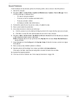
If sound problems are experienced, perform the following actions one at a time to correct the problem.
1.
Reboot the computer.
2.
Navigate to
Start
´
Control
Panel
´
System
and
Maintenance
´
System
´
Device
Manager
. Check
the Device Manager to determine that:
•
The device is properly installed.
•
There are no red Xs or yellow exclamation marks.
•
There are no device conflicts.
•
No hardware is listed under Other Devices.
3.
Roll back the audio driver to the previous version, if updated recently.
4.
Remove and reinstall the audio driver.
5.
Ensure that all volume controls are set mid range:
a.
Click the volume icon on the taskbar and drag the slider to 50. Ensure that the volume is not muted.
b.
Click Mixer to verify that other audio applications are set to 50 and not muted.
6.
Navigate to
Start
´
Control
Panel
´
Hardware
and
Sound
´
Sound
. Ensure that Speakers are selected
as the default audio device (green check mark).
NOTE:
If Speakers does not show, right-click on the
Playback
tab and select
Show
Disabled
Devices
(clear by default).
7.
Select Speakers and click
Configure
to start
Speaker
Setup
. Follow the onscreen prompts to configure
the speakers.
8.
Remove and recently installed hardware or software.
9.
Restore system and file settings from a known good date using
System
Restore
.
If the issue is not fixed, repeat the preceding steps and select an earlier time and date.
10.
Reinstall the Operating System.
11.
If the Issue is still not resolved, see “Online Support Information” on page 195.
Summary of Contents for Aspire 7230
Page 6: ...VI ...
Page 10: ...X Table of Contents ...
Page 92: ...82 Chapter 3 4 Grasp the Subwoofer Module and lift it up to remove ...
Page 94: ...84 Chapter 3 4 Lift the ExpressCard module away from the upper cover ...
Page 101: ...Chapter 3 91 4 Lift up the bezel and remove it from the LCD Module ...
Page 105: ...Chapter 3 95 5 Grasp the panel by both ends and lift to remove ...
Page 107: ...Chapter 3 97 4 Remove the LCD brackets by pulling away from the LCD Panel as shown ...
Page 110: ...100 Chapter 3 8 Connect the left and right Inverter cables 9 Connect the camera cable ...
Page 118: ...108 Chapter 3 4 Connect the two FFC cables as shown 5 Connect the cable as shown ...
Page 206: ...196 Appendix C ...

