150
Chapter 4
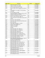
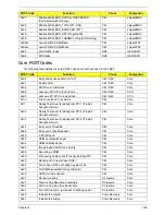
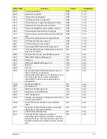
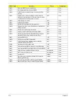
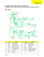
0x82
Initialize the CPU
Crisis Recovery
Core
0x89
Set Huge Segment
Crisis Recovery
Core
0x83
Initialize system timer
Crisis Recovery
Core
0x84
Initialize system I/O
Crisis Recovery
Core
0x88
Initialize Multi Processor
Crisis Recovery
Core
0x8A
Initialize OEM special code
Crisis Recovery
Core
0x8B
Initialize PIC and DMA
Crisis Recovery
Core
0x8C
Initialize Memory type
Crisis Recovery
Core
0x8D
Initialize Memory size
Crisis Recovery
Core
0x8F
Initialize SMM
Crisis Recovery
Core
0x90
System memory test
Crisis Recovery
Core
0x91
Initialize interrupt vectors
Crisis Recovery
Core
0x92
Initialize Run Time Clock
Crisis Recovery
Core
0x99
Initialize security
Crisis Recovery
Core
0x93
Initialize video
Crisis Recovery
Core
0x94
Output one beep
Crisis Recovery
Core
0x98
USB Initialization
Crisis Recovery
Core
0x95
Initialize the installed boot devices
Crisis Recovery
Core
0x96
Clear Huge segment
Crisis Recovery
Core
0x97
Boot Crisis Disk
Crisis Recovery
Core
0x20
DXE starts
DXE
Core
0x30
BIOSPSM
DXE
Core
0x02
BIOSBlockIO
DXE
Core
0x00
BIOSPSM Exception Handler - Divide error
BIOSPSM
Core
0x38
Cannot locate LegacyRegion DXE
BIOSPSM
Core
0xB1
ACPISupport driver Installed
DXE
Core
0xE0
BDS Entry
DXE
Core
0x07
IA32 variable driver entry
DXE
Core
0x0D
conspliter driver entry
DXE
Core
0x10
partition driver entry
DXE
Core
0x49
pciRootBridge driver entry
DXE
Core
0xC6
pciBusDriver entry
DXE
Core
0xE0
Go to legacy BIOS or BDS Entry Point
DXE
Core
0x90
Start Image
DXE
Core
0x90
Start Image Successfully
DXE
Core
0x90
Start Image Failed
DXE
Core
0x33
Debug Test driver for debug test PPI 1
DXE
Core
0x22
Debug Test driver for debug test PPI 2
DXE
Core
0x11
Debug Test driver for debug test PPI 3
DXE
Core
0x02
Invalid event # for measuring Separator Event
DXE
TCG
0x02
Invalid event # for measuring Separator Event
DXE
TCG
0x02
PCR Index over limit (PCR > 23)
DXE
TCG
0x02
TCG copy memory failed
DXE
TCG
POST Code
Function
Phase
Component
Summary of Contents for Aspire 7230
Page 6: ...VI ...
Page 10: ...X Table of Contents ...
Page 92: ...82 Chapter 3 4 Grasp the Subwoofer Module and lift it up to remove ...
Page 94: ...84 Chapter 3 4 Lift the ExpressCard module away from the upper cover ...
Page 101: ...Chapter 3 91 4 Lift up the bezel and remove it from the LCD Module ...
Page 105: ...Chapter 3 95 5 Grasp the panel by both ends and lift to remove ...
Page 107: ...Chapter 3 97 4 Remove the LCD brackets by pulling away from the LCD Panel as shown ...
Page 110: ...100 Chapter 3 8 Connect the left and right Inverter cables 9 Connect the camera cable ...
Page 118: ...108 Chapter 3 4 Connect the two FFC cables as shown 5 Connect the cable as shown ...
Page 206: ...196 Appendix C ...

