164
Chapter 6
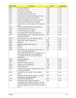
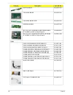
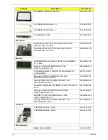
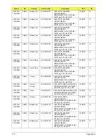
SWITCH BOARD
55.ARL07.003
TOUCHPAD BOARD
55.ARL07.004
TOUCHPAD BOARD W/FP
55.ARL07.005
EMPOWER BOARD
55.ARL07.006
MSI VGA Card nVidia NB9M-GS DDRII 256M 400MHz
32*16 MXM I w/ HDCP w/ Intersil PowerIC
VG.9MG06.001
MSI VGA Card nVidia NB9P-GS DDRIII 512M 800MHz
32*32 MXM II w/ HDCP w/ Intersil PowerIC
VG.9PG06.002
Cable
PWR CORD V943B30001218008 DANISH 3P
27.A03V7.006
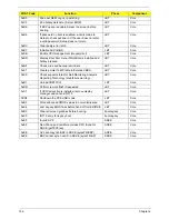
PWR CORD(ISR)1.8M 3PBLK FZ0I0008-038
27.TATV7.005
PWR CORD V50CB3T3012180QD TW-110V,3P
27.A99V7.002
POWER CORD(SWI)1.8M 3PBLACK FZ010008-011
27.A99V7.004
POWER CORD(IT) 1.8M 3PBLACK FZ010008-008
27.A99V7.005
POWER CORD(S.A) 1.8M 3BLACK FZ010008-006
27.T48V7.001
POWER CORD US 3PIN ROHS
27.TAXV7.001
POWER CORD(EU) 1.8M 3PBLACK FM010008-010
27.TATV7.001
POWER CORD(UK) 1.8M 3PBLACK FP010008-013
27.TATV7.003
BLUETOOTH CABLE
50.TPK07.001
NEW CARD CABLE
50.TPK07.002
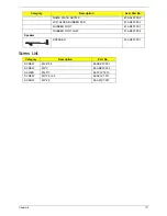
FFC CABLE - POWER/B TO MB
50.AR907.001
Category
Description
Acer Part No.
Summary of Contents for Aspire 7230
Page 6: ...VI ...
Page 10: ...X Table of Contents ...
Page 92: ...82 Chapter 3 4 Grasp the Subwoofer Module and lift it up to remove ...
Page 94: ...84 Chapter 3 4 Lift the ExpressCard module away from the upper cover ...
Page 101: ...Chapter 3 91 4 Lift up the bezel and remove it from the LCD Module ...
Page 105: ...Chapter 3 95 5 Grasp the panel by both ends and lift to remove ...
Page 107: ...Chapter 3 97 4 Remove the LCD brackets by pulling away from the LCD Panel as shown ...
Page 110: ...100 Chapter 3 8 Connect the left and right Inverter cables 9 Connect the camera cable ...
Page 118: ...108 Chapter 3 4 Connect the two FFC cables as shown 5 Connect the cable as shown ...
Page 206: ...196 Appendix C ...


