20
Chapter 1
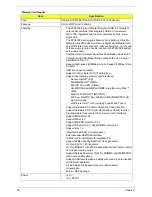
Crystal and Oscillator
Features (continued)
•
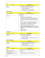
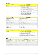
Fast ATA-133 IDE controller
•
NVIDIA® MediaShield™ RAID with support for RAID 0, RAID 1
•
IEEE 802.3 NVIDIA MAC for 1000BASE-T/100BASE-T/10BASE-T
Gigabit/Fast Ethernet/Ethernet. RGMII for Gigabit/Fast Ethernet/
Ethernet, aria. MII for Fast Ethernet/Ethernet
•
ASF 2.0 support for remote management
•
SPI Interface to Serial flash EEPROM
•
Able to load SBIOS and boot from SPI EEPROM without the use of
extra LPC-based EEPROM
•
TPM 1.2 support
•
Dual USB 2.0 EHCI and USB 1.1 OHCI (supports up to twelve
ports)
•
PCI 2.3 interface
•
Supports up to five PCI devices with dedicated REQ/GNT pairs
•
Dual SMBus 2.0 interfaces
•
UAA (Universal Audio Architecture) High Definition Audio (HDA)
interface
•
Supports up to two external UAA High Definition Audio codecs
for 7.1 channel audio
•
Supports 32-bit/192 kHz audio functionality
•
LPC bus 1.0 compatible interface
•
Integrated programmable clock synthesizer with spread spectrum
support
•
Support for Microsoft Vista ReadyDrive feature using commodity
hard-drives and flash devices
•
Support for direct input from accelerometer for more responsive
hard disk park control
•
ASF 2.0 support for remote manageability
•
Separately programmable spread spectrum support for key
interfaces including LVDS, SATA, HT
•
AMD CPU power sequencing protection logic
CPU core voltage
•
+NB_CORE for MCP77M CORE Power(+1.0V)
•
+1.1V_NB for MCP77M Hyper Transport Power
•
+1.1V for Hyper Transport, PCI-E, Sleep mode Core power, SATA
Interface, TV DAC supply
•
+1.8V for LVDS digital supply
•
+3.3V for PLL, CRTDAC, RGB DAC supply, USB Interface, CPU
Interface
•
LAN MAC, Display
Item
Specification
Features
•
32.768Khz crystal for RTC inside MCP77 and WINBOND
WPC8769LDG
•
25MHZ crystal for MCP77 controller
•
25MHZ crystal for BroadCom Lan controller BCM5764
Item
Specification
Summary of Contents for Aspire 7230
Page 6: ...VI ...
Page 10: ...X Table of Contents ...
Page 92: ...82 Chapter 3 4 Grasp the Subwoofer Module and lift it up to remove ...
Page 94: ...84 Chapter 3 4 Lift the ExpressCard module away from the upper cover ...
Page 101: ...Chapter 3 91 4 Lift up the bezel and remove it from the LCD Module ...
Page 105: ...Chapter 3 95 5 Grasp the panel by both ends and lift to remove ...
Page 107: ...Chapter 3 97 4 Remove the LCD brackets by pulling away from the LCD Panel as shown ...
Page 110: ...100 Chapter 3 8 Connect the left and right Inverter cables 9 Connect the camera cable ...
Page 118: ...108 Chapter 3 4 Connect the two FFC cables as shown 5 Connect the cable as shown ...
Page 206: ...196 Appendix C ...

