24
Chapter 1
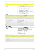
LCD 17.0”
KBC
Item
Specification
Vendor/model name
Samsung LTN170BT07-G01
Active Area (mm) /
Screen Diagonal (mm)
367.20(H) x 229.50(V)
17.0” diagonal
Display resolution (pixels)
1440 x 900 (Wide XGA+)
Pixel Pitch
0.255(H) x 0.255(V) (TYP.)
Pixel Arrangement
RGB vertical stripe
Display Mode
Normally white
Typical White Luminance (cd/m
2
)
also called Brightness
Minimum 190, Typical 220
Contrast Ratio
Minimum 300, Typical 500
Response Time (Optical Rise
Time/Fall Time) msec
Typical 8, Maximum 16
Nominal Input Voltage VDD
Minimum 3.0, Typical 3.3, Maximum 3.6
Typical Power Consumption (watt)
4. 68
Weight (g)
Typical 715, Maximum 735
Physical Size (mm)
382 (H) x 244.5 (V) x 6.7 (D)
Electrical Interface
LVDS
Support Color
262,144
Viewing Angle (degree)
Horizontal: Right/Left
Vertical: Upper/Lower
40, 45 / 40, 45
15, 20 / 20, 25
Temperature Range (°C)
Operating
Storage (shipping)
0 / 50
-20 / 60
Item
Specification
Chipset
WND WPCE775CA0DG
Features
•
Share BIOS memory
•
Support for SPI flash memories
•
Flash page programing support
•
Host-controlled CIR Port
•
High-accuracy, high-speed ADC
•
Up to 84 GPIO ports (including KB scanning) with a
variety of wake-up events
•
16 bit RISC core, with up to 4 Mbytes of external address
space, running at up to 25MHz
•
128 pin LQFP package
•
PC01 REV 1.0 and ACPI3.0 compliant.
•
Supports Microsoft® Advanced Power Management
(APM) Specifications Rev 1.2
Summary of Contents for Aspire 7230
Page 6: ...VI ...
Page 10: ...X Table of Contents ...
Page 92: ...82 Chapter 3 4 Grasp the Subwoofer Module and lift it up to remove ...
Page 94: ...84 Chapter 3 4 Lift the ExpressCard module away from the upper cover ...
Page 101: ...Chapter 3 91 4 Lift up the bezel and remove it from the LCD Module ...
Page 105: ...Chapter 3 95 5 Grasp the panel by both ends and lift to remove ...
Page 107: ...Chapter 3 97 4 Remove the LCD brackets by pulling away from the LCD Panel as shown ...
Page 110: ...100 Chapter 3 8 Connect the left and right Inverter cables 9 Connect the camera cable ...
Page 118: ...108 Chapter 3 4 Connect the two FFC cables as shown 5 Connect the cable as shown ...
Page 206: ...196 Appendix C ...

