30
Chapter 2
Information
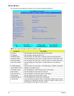
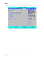
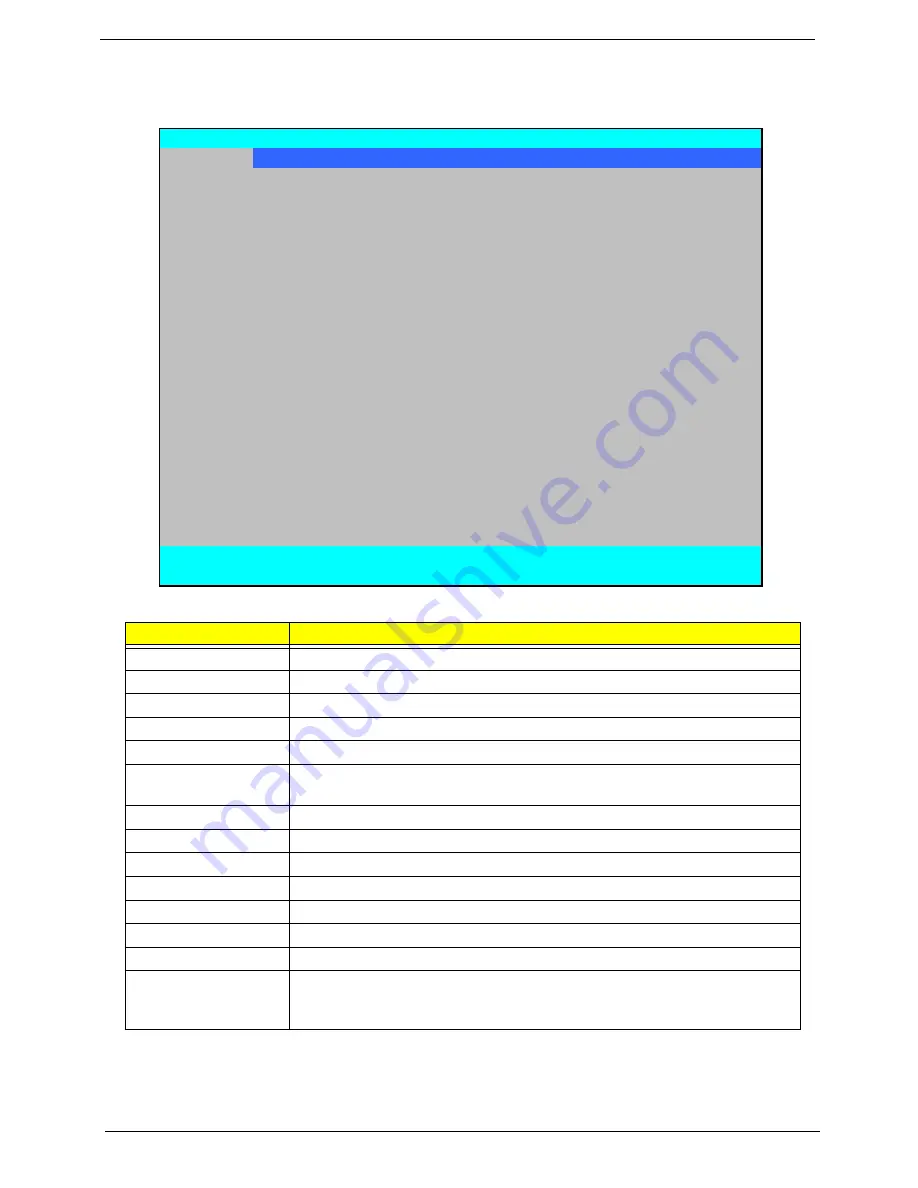
The Information screen displays a summary of your computer hardware information.
NOTE:
The system information is subject to different models.
Parameter
Description
CPU Type
This field shows the CPU type and speed of the system.
CPU Speed
This field shows the speed of the CPU.
IDE Model Name
This field shows the model name of HDD installed on primary IDE master.
IDE Serial Number
This field displays the serial number of HDD installed on primary IDE master.
IDE1 Model Name
This field shows the model name of HDD installed on secondary IDE master.
IDE1 Serial Number
This field displays the serial number of HDD installed on secondary IDE
master.
ATAPI Model Name
This field shows the model name of the Optical device installed in the system.
System BIOS Version
Displays system BIOS version.
VGA BIOS Version
This field displays the VGA firmware version of the system.
Serial Number
This field displays the serial number of this unit.
Asset Tag Number
This field displays the asset tag number of the system.
Product Name
This field shows product name of the system.
Manufacturer Name
This field displays the manufacturer of this system.
UUID Number
Universally Unique Identifier (UUID) is an identifier standard used in software
construction, standardized by the Open Software Foundation (OSF) as part of
the Distributed Computing Environment (DCE).
PhoenixBIOS Setup Utility
Information
Main Advanced
Security
Boot
Power
Exit
CPU Type:
AMD Turion(tm) Ultra Dual-Core Mobile ZM-82
CPU Speed:
2200 MHz
IDE Model Name:
ST9250827AS
IDE Serial Number:
5RG01N2C
IDE1 Model Name:
IDE1 Serial Number:
ATAPI Model Name:
Optiarc BD ROM BC-5500S
System BIOS Version:
V0.3103
VGA BIOS Version:
nVidia 62.77.15.00.09
Serial Number:
ZY50SK03C1815029FD2500
Asset Tag Number:
Product Name:
Manufacturer Name:
Acer
UUID:
00B7B9A32AC4DC1198AE001E683E8E30
F1
Help
↑↓
Select Item
F5/F6
Change Values
F9
Setup Defaults
ESC
Exit
←→
Select Menu
Enter
Select
X
Sub-Menu
F10
Save and Exit
Summary of Contents for Aspire 7230
Page 6: ...VI ...
Page 10: ...X Table of Contents ...
Page 92: ...82 Chapter 3 4 Grasp the Subwoofer Module and lift it up to remove ...
Page 94: ...84 Chapter 3 4 Lift the ExpressCard module away from the upper cover ...
Page 101: ...Chapter 3 91 4 Lift up the bezel and remove it from the LCD Module ...
Page 105: ...Chapter 3 95 5 Grasp the panel by both ends and lift to remove ...
Page 107: ...Chapter 3 97 4 Remove the LCD brackets by pulling away from the LCD Panel as shown ...
Page 110: ...100 Chapter 3 8 Connect the left and right Inverter cables 9 Connect the camera cable ...
Page 118: ...108 Chapter 3 4 Connect the two FFC cables as shown 5 Connect the cable as shown ...
Page 206: ...196 Appendix C ...

