Chapter 3
63
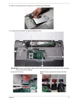
Removing the Switch Board
1.
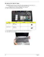
Remove the Switch Cover. See “Removing the Switch Cover” on page 62.
2.
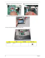
Lift the locking lever and remove the FFC cable on the left as shown.
3.
Disconnect both cables on the right as shown.
4.
Remove the two securing screws from the Switch Board and lift the board clear.
Step
Size
Quantity
Screw Type
Switch Board
M2*3 (NL)
2
Summary of Contents for Aspire 7230
Page 6: ...VI ...
Page 10: ...X Table of Contents ...
Page 92: ...82 Chapter 3 4 Grasp the Subwoofer Module and lift it up to remove ...
Page 94: ...84 Chapter 3 4 Lift the ExpressCard module away from the upper cover ...
Page 101: ...Chapter 3 91 4 Lift up the bezel and remove it from the LCD Module ...
Page 105: ...Chapter 3 95 5 Grasp the panel by both ends and lift to remove ...
Page 107: ...Chapter 3 97 4 Remove the LCD brackets by pulling away from the LCD Panel as shown ...
Page 110: ...100 Chapter 3 8 Connect the left and right Inverter cables 9 Connect the camera cable ...
Page 118: ...108 Chapter 3 4 Connect the two FFC cables as shown 5 Connect the cable as shown ...
Page 206: ...196 Appendix C ...

