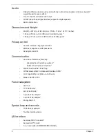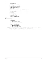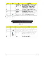
VIII
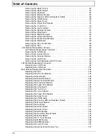
Table of Contents
Removing the Switch Cover . . . . . . . . . . . . . . . . . . . . . . . . . . . . . . . . . . . . . . . .62
Removing the Switch Board . . . . . . . . . . . . . . . . . . . . . . . . . . . . . . . . . . . . . . . .63
Removing the Keyboard . . . . . . . . . . . . . . . . . . . . . . . . . . . . . . . . . . . . . . . . . . .64
Removing the Modem Module . . . . . . . . . . . . . . . . . . . . . . . . . . . . . . . . . . . . . .65
Removing the Antenna, MIC and Speaker Cables . . . . . . . . . . . . . . . . . . . . . . .66
Removing the LCD Module . . . . . . . . . . . . . . . . . . . . . . . . . . . . . . . . . . . . . . . . .68
Removing the Upper Cover . . . . . . . . . . . . . . . . . . . . . . . . . . . . . . . . . . . . . . . .70
Removing the Finger Print Reader . . . . . . . . . . . . . . . . . . . . . . . . . . . . . . . . . . .74
Removing the Touch Pad . . . . . . . . . . . . . . . . . . . . . . . . . . . . . . . . . . . . . . . . . .76
Removing the Launch Board . . . . . . . . . . . . . . . . . . . . . . . . . . . . . . . . . . . . . . .77
Removing the Speaker Module . . . . . . . . . . . . . . . . . . . . . . . . . . . . . . . . . . . . . .78
Removing the eKey Board . . . . . . . . . . . . . . . . . . . . . . . . . . . . . . . . . . . . . . . . .79
Removing the Bluetooth board . . . . . . . . . . . . . . . . . . . . . . . . . . . . . . . . . . . . . .80
Removing the Subwoofer Module . . . . . . . . . . . . . . . . . . . . . . . . . . . . . . . . . . . .81
Removing the ExpressCard Module . . . . . . . . . . . . . . . . . . . . . . . . . . . . . . . . . .83
Removing the Mainboard . . . . . . . . . . . . . . . . . . . . . . . . . . . . . . . . . . . . . . . . . .85
Removing the CPU Fan Module . . . . . . . . . . . . . . . . . . . . . . . . . . . . . . . . . . . . .86
Removing the CPU . . . . . . . . . . . . . . . . . . . . . . . . . . . . . . . . . . . . . . . . . . . . . . .88
LCD Module Disassembly Process . . . . . . . . . . . . . . . . . . . . . . . . . . . . . . . . . . . . . .89
LCD Module Disassembly Flowchart . . . . . . . . . . . . . . . . . . . . . . . . . . . . . . . . .89
Removing the LCD Bezel . . . . . . . . . . . . . . . . . . . . . . . . . . . . . . . . . . . . . . . . . .90
Removing the Inverter Board . . . . . . . . . . . . . . . . . . . . . . . . . . . . . . . . . . . . . . .92
Removing the Camera Module . . . . . . . . . . . . . . . . . . . . . . . . . . . . . . . . . . . . . .93
Removing the LCD Panel . . . . . . . . . . . . . . . . . . . . . . . . . . . . . . . . . . . . . . . . . .94
Removing the LCD Brackets and FPC Cable . . . . . . . . . . . . . . . . . . . . . . . . . . .96
LCD Module Reassembly Procedure . . . . . . . . . . . . . . . . . . . . . . . . . . . . . . . . . . . . .98
Replacing the LCD Panel . . . . . . . . . . . . . . . . . . . . . . . . . . . . . . . . . . . . . . . . . .98
Replacing the LCD Bezel . . . . . . . . . . . . . . . . . . . . . . . . . . . . . . . . . . . . . . . . .101
Main Module Reassembly Procedure . . . . . . . . . . . . . . . . . . . . . . . . . . . . . . . . . . . .102
Replacing the CPU . . . . . . . . . . . . . . . . . . . . . . . . . . . . . . . . . . . . . . . . . . . . . .102
Replacing the CPU Fan Module . . . . . . . . . . . . . . . . . . . . . . . . . . . . . . . . . . . .102
Replacing the Mainboard . . . . . . . . . . . . . . . . . . . . . . . . . . . . . . . . . . . . . . . . .104
Replacing the Bluetooth Board . . . . . . . . . . . . . . . . . . . . . . . . . . . . . . . . . . . . .104
Replacing the ExpressCard Module . . . . . . . . . . . . . . . . . . . . . . . . . . . . . . . . .105
Replacing the Subwoofer Module . . . . . . . . . . . . . . . . . . . . . . . . . . . . . . . . . . .106
Replacing the Finger Print Reader . . . . . . . . . . . . . . . . . . . . . . . . . . . . . . . . . .107
Replacing the eKey Board . . . . . . . . . . . . . . . . . . . . . . . . . . . . . . . . . . . . . . . .109
Replacing the Touch Pad . . . . . . . . . . . . . . . . . . . . . . . . . . . . . . . . . . . . . . . . .110
Replacing the Launch Board . . . . . . . . . . . . . . . . . . . . . . . . . . . . . . . . . . . . . . .110
Replacing the Finger Print Reader . . . . . . . . . . . . . . . . . . . . . . . . . . . . . . . . . .111
Replacing the Upper Cover . . . . . . . . . . . . . . . . . . . . . . . . . . . . . . . . . . . . . . . .112
Replacing the LCD Module . . . . . . . . . . . . . . . . . . . . . . . . . . . . . . . . . . . . . . . .116
Replacing the Antenna, MIC and Speaker Cables . . . . . . . . . . . . . . . . . . . . . .117
Replacing the Modem Module . . . . . . . . . . . . . . . . . . . . . . . . . . . . . . . . . . . . .119
Replacing the Keyboard . . . . . . . . . . . . . . . . . . . . . . . . . . . . . . . . . . . . . . . . . .120
Replacing the Switch Board . . . . . . . . . . . . . . . . . . . . . . . . . . . . . . . . . . . . . . .121
Replacing the Switch Cover . . . . . . . . . . . . . . . . . . . . . . . . . . . . . . . . . . . . . . .122
Replacing the ODD Module . . . . . . . . . . . . . . . . . . . . . . . . . . . . . . . . . . . . . . .123
Replacing the Hard Disk Drive Module . . . . . . . . . . . . . . . . . . . . . . . . . . . . . . .123
Replacing the WLAN Board . . . . . . . . . . . . . . . . . . . . . . . . . . . . . . . . . . . . . . .125
Replacing the TV Tuner Module . . . . . . . . . . . . . . . . . . . . . . . . . . . . . . . . . . . .125
Replacing the MXM Module . . . . . . . . . . . . . . . . . . . . . . . . . . . . . . . . . . . . . . .126
Replacing the DIMM Modules . . . . . . . . . . . . . . . . . . . . . . . . . . . . . . . . . . . . . .126
Replacing the Lower Covers . . . . . . . . . . . . . . . . . . . . . . . . . . . . . . . . . . . . . . .127
Replacing the ExpressCard Dummy Tray . . . . . . . . . . . . . . . . . . . . . . . . . . . . .127
Summary of Contents for Aspire 7230
Page 6: ...VI ...
Page 10: ...X Table of Contents ...
Page 92: ...82 Chapter 3 4 Grasp the Subwoofer Module and lift it up to remove ...
Page 94: ...84 Chapter 3 4 Lift the ExpressCard module away from the upper cover ...
Page 101: ...Chapter 3 91 4 Lift up the bezel and remove it from the LCD Module ...
Page 105: ...Chapter 3 95 5 Grasp the panel by both ends and lift to remove ...
Page 107: ...Chapter 3 97 4 Remove the LCD brackets by pulling away from the LCD Panel as shown ...
Page 110: ...100 Chapter 3 8 Connect the left and right Inverter cables 9 Connect the camera cable ...
Page 118: ...108 Chapter 3 4 Connect the two FFC cables as shown 5 Connect the cable as shown ...
Page 206: ...196 Appendix C ...


