76
Chapter 3
20.
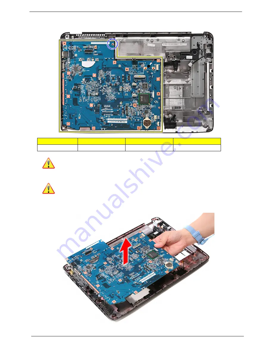
Remove the one screw (H) securing the main board in place.
Note:
RTC battery has been highlighted with the yellow circle as shown in the figure above. Please
detach the RTC battery and follow local regulations for disposal.
Note:
Circuit boards > 10cm
2
has been highlighted with the yellow square as shown in the figure
above. Please detach the circuit boards and follow the local regulations for disposal.
21.
Lift the main board gently and remove it carefully from the lower case..
Size (Quantity)
Color
Torque
Part No.
M2 x L3 (1)
Silver
1.6 kgf-cm
86.9A552.3R0
Summary of Contents for Aspire 7336 Series
Page 6: ...VI ...
Page 12: ...4 Chapter 1 System Block Diagram For Aspire 7736 7736Z 7336 Series ...
Page 13: ...Chapter 1 5 For Aspire 7540 Series ...
Page 120: ...112 Chapter 6 Aspire 7736 7736Z 7336 Series and Aspire 7540 Series Exploded Diagram ...
Page 151: ...Appendix A 143 Model Definition and Configuration Appendix A ...
Page 182: ...174 Appendix B ...
Page 184: ...176 Appendix C ...
Page 187: ...www s manuals com ...


