Chapter 4
141
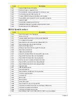
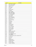
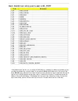
0x3B
MONOTONIC_COUNTER
0x3C
WATCH_DOG_TIMER
0x3D
SECURITY_STUB
0x3E
DXE_CPU_IO
0x3F
CF9_RESET
0x40
PC_RTC
0x41
STATUS_CODE
0x42
VARIABLE
0x43
EMU_VARIABLE
0x44
DXE_CHIPSET_INIT
0x45
DXE_ALERT_FORMAT
0x46
PCI_HOST_BRIDGE
0x47
PCI_EXPRESS
0x48
DXE_SB_INIT
0x49
IDE_CONTROLLER
0x4A
SATA_CONTROLLER
0x4B
SB_SM_BUS
0x4C
ISA_ACPI_DRIVER
0x4D
ISA_BUS
0x4E
ISA_SERIAL
0x4F
IDE_BUS
0x50
PCI_BUS
0x51
BOOT_PRIORITY
0x52
FVB_SERVICE
0x53
ACPI_PLATFORM
0x54
PCI_HOT_PLUG
0x55
DXE_PLATFORM
0x56
PLATFORM_IDE
0x57
SMBIOS
0x58
MEMORY_SUB_CLASS
0x59
MISC_SUB_CLASS
0x5A
CON_PLATFORM
0x5B
SAVE_MEMORY_CONFIG
0x5C
ACPI_SUPPORT
0x5D
CON_SPLITTER_UGA_VGA / CON_SPLITTER
0x5E
VGA_CLASS
0x5F
DATA_HUB
0x60
DISK_IO
0x61
MEMORY_TEST
0x62
CRISIS_RECOVERY
0x63
LEGACY_8259
0x64
LEGACY_REGION
0x65
LEGACY_INTERRUPT
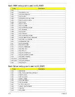
Code
Description
Summary of Contents for Aspire 7715Z Series
Page 6: ...VI ...
Page 10: ...X Table of Contents ...
Page 13: ...Chapter 1 3 System Block Diagram ...
Page 30: ...20 Chapter 1 ...
Page 52: ...42 Chapter 2 ...
Page 74: ...64 Chapter 3 4 Disconnect the following four cables from the Mainboard A B C D ...
Page 87: ...Chapter 3 77 4 Using both hands lift the Thermal Module clear of the Mainboard ...
Page 89: ...Chapter 3 79 4 Lift the CPU Fan clear of the Mainboard as shown ...
Page 95: ...Chapter 3 85 5 Lift the LCD Panel clear of the module ...
Page 103: ...Chapter 3 93 9 The Antennas and cables appear as shown when correctly installed ...
Page 108: ...98 Chapter 3 2 Replace the four screws and screw caps provided ...
Page 113: ...Chapter 3 103 5 Replace the FFC and press down as indicated to secure it to the Upper Cover ...
Page 124: ...114 Chapter 3 17 Replace the two screws securing the LCD Module to the Lower Cover ...
Page 132: ...122 Chapter 3 ...
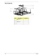
Page 164: ...154 Chapter 6 Rear Assembly No Description Acer P N 1 HDD Cover 2 3 RAM Cover 4 5 1 2 3 4 5 ...
Page 174: ...Appendix A 164 Model Definition and Configuration Appendix A ...
Page 196: ...186 Appendix C ...
Page 200: ...190 ...

