Chapter 4
143
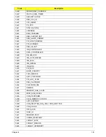
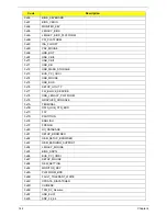
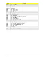
0x91
DXE_0x91 PXE_BC
0x92
PXE_DHCP4
0x93
EBC
0x94~0x9F
RESERVED
0xA0
DXE_H2O_DEBUG_IO
0xA1
DXE_H2O_DEBUG_IO
0xA2
DXE_TPM_TCG
0xA3
DXE_TPM_PHYSICAL_PRESENCE
0xA4
DXE_OEM_SERVICE
0xA5
DXE_EVENT_LOG
0xA6
DXE_ SECURITY_HDD_PASSWORD_SERVICE
0xA7
DXE_LAN_ASF_INIT
0xA8
DXE_BUS_PCI_SERIAL
0xA9
DXE_LAN_IDER_CONTROLLER
0xAA
DXE_LAN_AMT
0xAB
DXE_ SECURITY_SYSTEM_PASSWORD_SERVICE
0xAC
DXE_ SECURITY_ PASSWORD_CONSOLE
0xAD
DXE_ DATA_HUB_RECORD_POLICY
0xAE
DXE_TPM_DRIVER
0xAF
RESERVED
0xB0
JAPANESE
0xB1
DXE_UNICODE_COLLACTION
Code
Description
Summary of Contents for Aspire 7715Z Series
Page 6: ...VI ...
Page 10: ...X Table of Contents ...
Page 13: ...Chapter 1 3 System Block Diagram ...
Page 30: ...20 Chapter 1 ...
Page 52: ...42 Chapter 2 ...
Page 74: ...64 Chapter 3 4 Disconnect the following four cables from the Mainboard A B C D ...
Page 87: ...Chapter 3 77 4 Using both hands lift the Thermal Module clear of the Mainboard ...
Page 89: ...Chapter 3 79 4 Lift the CPU Fan clear of the Mainboard as shown ...
Page 95: ...Chapter 3 85 5 Lift the LCD Panel clear of the module ...
Page 103: ...Chapter 3 93 9 The Antennas and cables appear as shown when correctly installed ...
Page 108: ...98 Chapter 3 2 Replace the four screws and screw caps provided ...
Page 113: ...Chapter 3 103 5 Replace the FFC and press down as indicated to secure it to the Upper Cover ...
Page 124: ...114 Chapter 3 17 Replace the two screws securing the LCD Module to the Lower Cover ...
Page 132: ...122 Chapter 3 ...
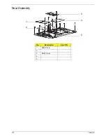
Page 164: ...154 Chapter 6 Rear Assembly No Description Acer P N 1 HDD Cover 2 3 RAM Cover 4 5 1 2 3 4 5 ...
Page 174: ...Appendix A 164 Model Definition and Configuration Appendix A ...
Page 196: ...186 Appendix C ...
Page 200: ...190 ...

