Chapter 6
161
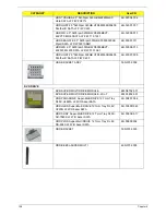
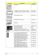
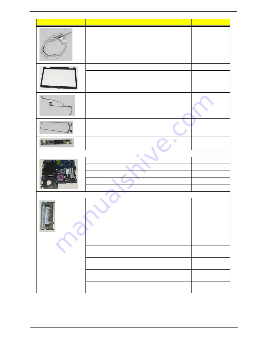
ANTENNA AUX
50.N3702.004
LCD BEZEL FOR W/CCD FUNCTION - ASPIRE
60.PL602.004
LCD BEZEL FOR W/O CCD FUNCTION - ASPIRE
60.PL502.001
LED CABLE FOR W/CCD F
60.N3702.006
LCD BRACKET R&L FOR LED F
33.N3702.004
CAMERA 0.3
57.N2802.001
MAINBOARD
MB ASSY-GM45(B3)-INTEL
MB.N5302.001
MB ASSY-GM45(A1)-INTEL
TBD
MB ASSY-GL40-(B3)-INTEL
TBD
Mainboard AS7715Z Intel GL40 ICH9M V1.0 LF
MB.PL402.001
Mainboard G525 Intel GL40 ICH9M V1.0 LF DDR3
MB.N8302.001
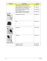
MEMORY
Memory NANYA SO-DIMM DDRII 667 1GB
NT1GT64UH8D0FN-3C LF 64*16 0.07um
KN.1GB03.026
Memory MICRON SO-DIMM DDRII 667 1GB
MT8HTF12864HDY-667G1 LF 64*16 0.065um
KN.1GB04.010
Memory ELPIDA SO-DIMM DDRII 667 1GB
EBE11UE6ACUA-6E-E LF 64*16 0.065um
KN.1GB09.008
Memory SAMSUNG SO-DIMM DDRII 667 1GB
M470T2864EH3-CE6 LF 64*16 0.055um
KN.1GB0B.027
Memory HYNIX SO-DIMM DDRII 667 1GB
HYMP112S64CP6-Y5 LF
KN.1GB0G.012
Memory HYNIX SO-DIMM DDRII 667 1GB
HMP112S6EFR6C-Y5 LF 64*16 0.055um
KN.1GB0G.022
Memory NANYA SO-DIMM DDRII 667 2GB
NT2GT64U8HD0BN-3C LF 128*8 0.07um
KN.2GB03.011
Memory MICRON SO-DIMM DDRII 667 2GB
MT16HTF25664HY-667G1 LF 128*8 0.065um
KN.2GB04.010
CATEGORY
DESCRIPTION
AcerPN
Summary of Contents for Aspire 7715Z Series
Page 6: ...VI ...
Page 10: ...X Table of Contents ...
Page 13: ...Chapter 1 3 System Block Diagram ...
Page 30: ...20 Chapter 1 ...
Page 52: ...42 Chapter 2 ...
Page 74: ...64 Chapter 3 4 Disconnect the following four cables from the Mainboard A B C D ...
Page 87: ...Chapter 3 77 4 Using both hands lift the Thermal Module clear of the Mainboard ...
Page 89: ...Chapter 3 79 4 Lift the CPU Fan clear of the Mainboard as shown ...
Page 95: ...Chapter 3 85 5 Lift the LCD Panel clear of the module ...
Page 103: ...Chapter 3 93 9 The Antennas and cables appear as shown when correctly installed ...
Page 108: ...98 Chapter 3 2 Replace the four screws and screw caps provided ...
Page 113: ...Chapter 3 103 5 Replace the FFC and press down as indicated to secure it to the Upper Cover ...
Page 124: ...114 Chapter 3 17 Replace the two screws securing the LCD Module to the Lower Cover ...
Page 132: ...122 Chapter 3 ...
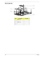
Page 164: ...154 Chapter 6 Rear Assembly No Description Acer P N 1 HDD Cover 2 3 RAM Cover 4 5 1 2 3 4 5 ...
Page 174: ...Appendix A 164 Model Definition and Configuration Appendix A ...
Page 196: ...186 Appendix C ...
Page 200: ...190 ...

