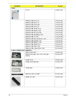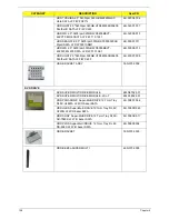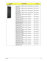
162
Chapter 6
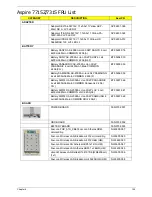
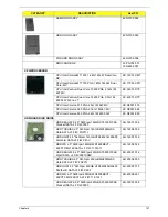
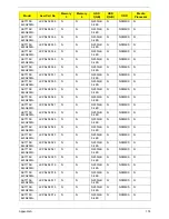
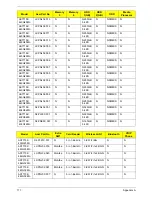
Memory ELPIDA SO-DIMM DDRII 667 2GB
EBE21UE8ACUA-6E-E LF 128*8 0.07um
KN.2GB09.001
Memory SAMSUNG SO-DIMM DDRII 667 2GB
M470T5663EH3-CE6 LF 128*8 0.055um
KN.2GB0B.011
Memory HYNIX SO-DIMM DDRII 667 2GB
HYMP125S64CP8-Y5 LF
KN.2GB0G.004
Memory HYNIX SO-DIMM DDRII 667 2GB
HMP125S6EFR8C-Y5 LF 128*8 0.055um
KN.2GB0G.012
HEATSINK
THERMAL MODULE-INTEL
60.N3702.007
FAN
23.N3702.001
SPEAKER
SPEAKER R
23.N3702.002
SPEAKER L
23.N3702.003
MISCELLANEOUS
NAME PLATE-AS7715
40.PL502.001
NAME PLATE-AS7315
40.PL802.001
CATEGORY
DESCRIPTION
AcerPN
Summary of Contents for Aspire 7715Z Series
Page 6: ...VI ...
Page 10: ...X Table of Contents ...
Page 13: ...Chapter 1 3 System Block Diagram ...
Page 30: ...20 Chapter 1 ...
Page 52: ...42 Chapter 2 ...
Page 74: ...64 Chapter 3 4 Disconnect the following four cables from the Mainboard A B C D ...
Page 87: ...Chapter 3 77 4 Using both hands lift the Thermal Module clear of the Mainboard ...
Page 89: ...Chapter 3 79 4 Lift the CPU Fan clear of the Mainboard as shown ...
Page 95: ...Chapter 3 85 5 Lift the LCD Panel clear of the module ...
Page 103: ...Chapter 3 93 9 The Antennas and cables appear as shown when correctly installed ...
Page 108: ...98 Chapter 3 2 Replace the four screws and screw caps provided ...
Page 113: ...Chapter 3 103 5 Replace the FFC and press down as indicated to secure it to the Upper Cover ...
Page 124: ...114 Chapter 3 17 Replace the two screws securing the LCD Module to the Lower Cover ...
Page 132: ...122 Chapter 3 ...
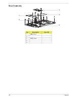
Page 164: ...154 Chapter 6 Rear Assembly No Description Acer P N 1 HDD Cover 2 3 RAM Cover 4 5 1 2 3 4 5 ...
Page 174: ...Appendix A 164 Model Definition and Configuration Appendix A ...
Page 196: ...186 Appendix C ...
Page 200: ...190 ...

