184
Appendix B
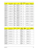
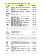
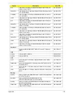
HYNIX
Memory HYNIX SO-DIMM DDRII 667 1GB HMP112S6EFR6C-Y5
LF 64*16 0.055um
KN.1GB0G.022
NANYA
Memory NANYA SO-DIMM DDRII 667 2GB NT2GT64U8HD0BN-
3C LF 128*8 0.07um
KN.2GB03.011
MICRON
Memory MICRON SO-DIMM DDRII 667 2GB MT16HTF25664HY-
667G1 LF 128*8 0.065um
KN.2GB04.010
ELPIDA
Memory ELPIDA SO-DIMM DDRII 667 2GB EBE21UE8ACUA-
6E-E LF 128*8 0.07um
KN.2GB09.001
SAMSUNG
Memory SAMSUNG SO-DIMM DDRII 667 2GB M470T5663EH3-
CE6 LF 128*8 0.055um
KN.2GB0B.011
HYNIX
Memory HYNIX SO-DIMM DDRII 667 2GB HMP125S6EFR8C-
Y5 LF 128*8 0.055um
KN.2GB0G.012
HYNIX
Memory HYNIX SO-DIMM DDRII 667 1GB HYMP112S64CP6-Y5
LF
KN.1GB0G.012
HYNIX
Memory HYNIX SO-DIMM DDRII 667 2GB HYMP125S64CP8-Y5
LF
KN.2GB0G.004
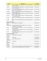
Northbridge Chipset
INTEL
NB Chipset Intel CS GL40NB A1
KI.G4501.009
ODD
PANASONIC
ODD PANASONIC Super-Multi DRIVE 12.7mm Tray DL 8X
UJ880A LF W/O bezel SATA
KU.00807.064
HLDS
ODD HLDS Super-Multi DRIVE 12.7mm Tray DL 8X GT20N LF
W/O bezel SATA
KU.0080D.040
SONY
ODD SONY Super-Multi DRIVE 12.7mm Tray DL 8X AD-7580S
LF W/O bezel SATA
KU.0080E.017
PLDS
ODD PLDS Super-Multi DRIVE 12.7mm Tray DL 8X DS-8A3S LF
W/O bezel SATA
KU.0080F.004
Southbridge Chipset
INTEL
SB Chipset Intel CS ICH9M
KI.80101.030
Software
Norton
Norton 360
SR.23900.005
Norton
Antivirus application NIS
SR.23900.002
VGA Chip
N/A
UMA (Intel)
KI.23200.038
Antenna
WNC
PIFA
LZ.23500.006
WLAN
Foxconn
Foxconn FOX_ATH_XB63 Foxconn Atheros XB63 minicard b/g
NI.23600.007
Foxconn
Foxconn Wireless LAN Broadcom 4312 minicard b/g
NI.23600.029
Vendor
Description
Acer P/N
Summary of Contents for Aspire 7715Z Series
Page 6: ...VI ...
Page 10: ...X Table of Contents ...
Page 13: ...Chapter 1 3 System Block Diagram ...
Page 30: ...20 Chapter 1 ...
Page 52: ...42 Chapter 2 ...
Page 74: ...64 Chapter 3 4 Disconnect the following four cables from the Mainboard A B C D ...
Page 87: ...Chapter 3 77 4 Using both hands lift the Thermal Module clear of the Mainboard ...
Page 89: ...Chapter 3 79 4 Lift the CPU Fan clear of the Mainboard as shown ...
Page 95: ...Chapter 3 85 5 Lift the LCD Panel clear of the module ...
Page 103: ...Chapter 3 93 9 The Antennas and cables appear as shown when correctly installed ...
Page 108: ...98 Chapter 3 2 Replace the four screws and screw caps provided ...
Page 113: ...Chapter 3 103 5 Replace the FFC and press down as indicated to secure it to the Upper Cover ...
Page 124: ...114 Chapter 3 17 Replace the two screws securing the LCD Module to the Lower Cover ...
Page 132: ...122 Chapter 3 ...
Page 164: ...154 Chapter 6 Rear Assembly No Description Acer P N 1 HDD Cover 2 3 RAM Cover 4 5 1 2 3 4 5 ...
Page 174: ...Appendix A 164 Model Definition and Configuration Appendix A ...
Page 196: ...186 Appendix C ...
Page 200: ...190 ...

