188
Removing
58
Replacing
115
Keyboard Failure
127
L
LCD Bezel
Removing
82
Replacing
97
LCD Brackets
Removing
86
Replacing
94
LCD Cable
Replacing
94
LCD Failure
127
LCD Module
Removing
59
Replacing
110
LCD Module Disassembly
Flowchart
81
LCD Module Reassembly Procedure
91
LCD Panel
Removing
84
Replacing
94
Left Speaker Module
Removing
68
Replacing
105
Lower Covers
Removing
48
Replacing
119
M
Main Unit Disassembly
Flowchart
56
Mainboard
Removing
74
Replacing
101
media access
on indicator
5, 8
Memory
Removing
51
Replacing
118
Memory Check
124
Model Definition
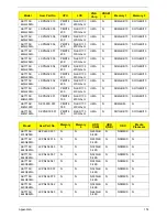
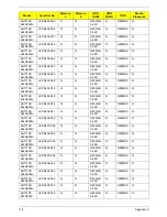
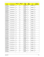
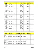
164
N
No Display Issue
125
num lock
on indicator
5, 8
O
ODD Failure
131
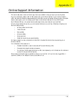
Online Support Information
185
Optical Disk Drive
Replacing
119
Optical Drive Module
Removing
49
P
Panel
4
Bottom
7
PC Card
8
Power Board
Removing
67
Replacing
106
Power On Failure
124
R
Replacing
104, 105
Right Speaker Module
Removing
70
Replacing
104
RTC Battery
Removing
75
S
SD Dummy Card
Removing
47
Replacing
120
Speakers
104, 105
Removing
68, 70
Switch Cover
Removing
57
Replacing
116
System
Block Diagram
3
T
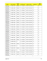
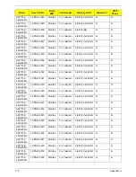
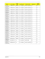
Test Compatible Components
181
Thermal Module
Removing
76
Replacing
100
Summary of Contents for Aspire 7715Z Series
Page 6: ...VI ...
Page 10: ...X Table of Contents ...
Page 13: ...Chapter 1 3 System Block Diagram ...
Page 30: ...20 Chapter 1 ...
Page 52: ...42 Chapter 2 ...
Page 74: ...64 Chapter 3 4 Disconnect the following four cables from the Mainboard A B C D ...
Page 87: ...Chapter 3 77 4 Using both hands lift the Thermal Module clear of the Mainboard ...
Page 89: ...Chapter 3 79 4 Lift the CPU Fan clear of the Mainboard as shown ...
Page 95: ...Chapter 3 85 5 Lift the LCD Panel clear of the module ...
Page 103: ...Chapter 3 93 9 The Antennas and cables appear as shown when correctly installed ...
Page 108: ...98 Chapter 3 2 Replace the four screws and screw caps provided ...
Page 113: ...Chapter 3 103 5 Replace the FFC and press down as indicated to secure it to the Upper Cover ...
Page 124: ...114 Chapter 3 17 Replace the two screws securing the LCD Module to the Lower Cover ...
Page 132: ...122 Chapter 3 ...
Page 164: ...154 Chapter 6 Rear Assembly No Description Acer P N 1 HDD Cover 2 3 RAM Cover 4 5 1 2 3 4 5 ...
Page 174: ...Appendix A 164 Model Definition and Configuration Appendix A ...
Page 196: ...186 Appendix C ...
Page 200: ...190 ...

