Chapter 1
13
Hardware Specifications and Configurations
Processor
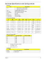
Processor Specifications
CPU Fan True Value Table
•
Throttling 50%: On=99°C, Off=96°C
•
OS Shutdown: 105°C
•
H/W Shutdown: 110°C
Northbridge
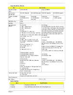
Item
Specification
CPU
•
Intel® Pentium® mobile processor*
•
Intel® Celeron® mobile processor*
Type
Intel Mobile Memron uPGA
Core Logic
Mobile Intel® GL40 Express Chipset
CPU Package
Micro uPGA-478 Package
Power
65 Watts
On-die Cache
4MB L2 cache
Front Side Bus
667/800/1066MHz
Item
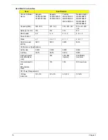
CPU
Speed
Cores
Bus
Speed
Mfg
Tech
Cache
Size
Package
Core
Voltage
Acer P/N
T1600
1.66 GHz
2
667 MHz
65 nm
1 MB
PGA
1.075V-
1.175V
KC.16001.CMT
T1700
1.83 GHz
2
667 MHz
65 nm
1 MB
PGA
1.075V-
1.175V
KC.17001.CMT
CM575
2.0 GHz
2
667 MHz
65 nm
1 MB
PGA
0.95-
1.30V
KC.N0001.575
CM585
2.16 GHz
2
667 MHz
65 nm
1 MB
PGA
0.95-
1.30V
KC.N0001.585
CM900
2.2 GHz
2
800 MHz
N/A
1 MB
PGA
N/A
KC.N0001.900
PMDT4300
2.16 GHz
2
667 MHz
N/A
1 MB
PGA
N/A
KC.34001.DT
P
PMDT4400
2.0 GHz
2
800 MHz
N/A
1 MB
PGA
N/A
KC.42001.DT
P
Fan On Temp (°C)
Fan Speed (rpm)
SPL Spec (dBA)
45
3000
28
50
3300
31
55
3700
34
65
4100
37
75
4500
40
80
4500
40
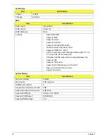
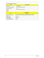
Item
Specification
Chipset
Intel Cantiga GM45/GL40
Package
uFCBGA-1329
Summary of Contents for Aspire 7715Z Series
Page 6: ...VI ...
Page 10: ...X Table of Contents ...
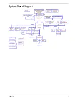
Page 13: ...Chapter 1 3 System Block Diagram ...
Page 30: ...20 Chapter 1 ...
Page 52: ...42 Chapter 2 ...
Page 74: ...64 Chapter 3 4 Disconnect the following four cables from the Mainboard A B C D ...
Page 87: ...Chapter 3 77 4 Using both hands lift the Thermal Module clear of the Mainboard ...
Page 89: ...Chapter 3 79 4 Lift the CPU Fan clear of the Mainboard as shown ...
Page 95: ...Chapter 3 85 5 Lift the LCD Panel clear of the module ...
Page 103: ...Chapter 3 93 9 The Antennas and cables appear as shown when correctly installed ...
Page 108: ...98 Chapter 3 2 Replace the four screws and screw caps provided ...
Page 113: ...Chapter 3 103 5 Replace the FFC and press down as indicated to secure it to the Upper Cover ...
Page 124: ...114 Chapter 3 17 Replace the two screws securing the LCD Module to the Lower Cover ...
Page 132: ...122 Chapter 3 ...
Page 164: ...154 Chapter 6 Rear Assembly No Description Acer P N 1 HDD Cover 2 3 RAM Cover 4 5 1 2 3 4 5 ...
Page 174: ...Appendix A 164 Model Definition and Configuration Appendix A ...
Page 196: ...186 Appendix C ...
Page 200: ...190 ...

