Chapter 2
23
Main
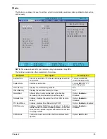
The Main screen allows the user to set the system time and date as well as enable and disable boot option
and recovery.
NOTE:
The screen above is for your reference only. Actual values may differ.
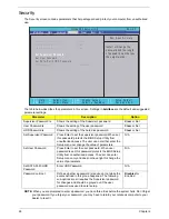
The table below describes the parameters in this screen.
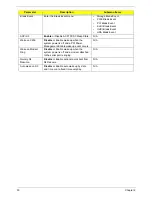
Parameter
Description
Format/Option
System Time
Sets the system time. The hours are displayed with 24-
hour format.
Format: HH:MM:SS
(hour:minute:second)
System Date
Sets the system date.
Format MM/DD/YYYY
(month/day/year)
Total Memory
Displays the total memory available.
N/A
Video Memory
Displays the available memory for Video.
N/A
Quick Boot
Allows startup to skip certain tests while booting,
decreasing the time needed to boot the system.
Option:
Enabled
or
Disabled
Network Boot
Enables, disables the system boot from LAN (remote
server).
Option:
Enabled
or
Disabled
F12 Boot Menu
Enables, disables Boot Menu during POST.
Option:
Enabled
or Enabled
D2D Recovery
Enables, disables D2D Recovery function. The function
allows the user to create a hidden partition on hard disc
drive to store operation system and restore the system
to factory defaults.
Option:
Enabled
or
Disabled
SATA Mode
Control the mode in which the SATA controller should
operate.
Option:
AHCI
or IDE
I t e m S p e c i f i c H e l p
T h i s i s t h e h e l p f o r t h e
h o u r f i e l d . V a l i d r a n g e
i s f r o m 0 t o 2 3 .
I N C R E A S E / R E D U C E : F 5 / F 6
F 1
E S C
H e l p
E x i t
S e l e c t I t e m
S e l e c t M e n u
C h a n g e Va l u e s
S e l e c t
S u b M e n u
E n t e r
F 9
F 1 0
S e t u p D e f a u l t
S a v e a n d E x i t
[ 1 9 : 1 0 : 5 9 ]
[ 0 1 / 0 9 / 2 0 0 9 ]
4 0 9 5 M B
5 1 2 M B
[ E n a b l e d ]
[ E n a b l e d ]
[ D i s a b l e d ]
[ E n a b l e d ]
[ A H C I ]
[ 1 9 :
1 0 : 5 9 ]
[ 0 1 / 0 9 / 2 0 0 9 ]
4 0 9 5 M B
5 1 2 M B
[ E n a b l e d ]
[ E n a b l e d ]
[ D i s a b l e d ]
[ E n a b l e d ]
[ A H C I ]
S y s t e m T i m e :
S y s t e m D a t e :
T o t a l M e m o r y :
V i d e o M e m o r y :
Q u i c k B o o t
N e t w o r k B o o t
F 1 2 B o o t M e n u
D 2 D R e c o v e r y
S A T A M o d e
S y s t e m T i m e :
S y s t e m D a t e :
T o t a l M e m o r y :
V i d e o M e m o r y :
Q u i c k B o o t
N e t w o r k B o o t
F 1 2 B o o t M e n u
D 2 D R e c o v e r y
S A T A M o d e
F 5 / F 6
I n s y d e H 2 0 S e t u p U t i l i t y R e v . 3 . 5
Boot
Exit
Security
Information
Advanced
Power
Main
Summary of Contents for Aspire 7715Z Series
Page 6: ...VI ...
Page 10: ...X Table of Contents ...
Page 13: ...Chapter 1 3 System Block Diagram ...
Page 30: ...20 Chapter 1 ...
Page 52: ...42 Chapter 2 ...
Page 74: ...64 Chapter 3 4 Disconnect the following four cables from the Mainboard A B C D ...
Page 87: ...Chapter 3 77 4 Using both hands lift the Thermal Module clear of the Mainboard ...
Page 89: ...Chapter 3 79 4 Lift the CPU Fan clear of the Mainboard as shown ...
Page 95: ...Chapter 3 85 5 Lift the LCD Panel clear of the module ...
Page 103: ...Chapter 3 93 9 The Antennas and cables appear as shown when correctly installed ...
Page 108: ...98 Chapter 3 2 Replace the four screws and screw caps provided ...
Page 113: ...Chapter 3 103 5 Replace the FFC and press down as indicated to secure it to the Upper Cover ...
Page 124: ...114 Chapter 3 17 Replace the two screws securing the LCD Module to the Lower Cover ...
Page 132: ...122 Chapter 3 ...
Page 164: ...154 Chapter 6 Rear Assembly No Description Acer P N 1 HDD Cover 2 3 RAM Cover 4 5 1 2 3 4 5 ...
Page 174: ...Appendix A 164 Model Definition and Configuration Appendix A ...
Page 196: ...186 Appendix C ...
Page 200: ...190 ...

