Chapter 2
25
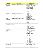
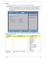
Video
Configuration
Enter the Video Configuration menu.
•
Render Standby
•
IGD—Device2, Function1
•
IGD—Pre-allocat Memory
•
IGD—DVMT Size
•
Clock Chip Initialize
•
Enabled CK SSC
•
IGD—Boot Type
•
IGD—LCD Panel Type
•
IGD—TV
•
IGD—PAVP Mode
USB Configuration
Enter the USB Configuration menu.
•
USB Legacy
•
EHCI 1, 2
•
UHCI 1 ~ 5
•
Per-Port Control
•
USB Port 0~7
Chipset
Configuration
Enter the Chipset Configuration menu.
•
Port 80h Cycles
•
DMI Link ASPM Control
•
Automatic ASPM
•
PCI Latency Timer
•
VT-d
•
iTPM
ACPI Table/
Features Control
Enter the ACPI Table/Features Control
menu.
•
FACP—C2 Latency Value
•
FACP—C3 Latency Value
•
FACP—RTC S4 Wakeup
•
APIC—IO APIC Mode
•
HPET—HPET Support
• Base Address select
Express Card
•
N/A
PCI EXpress Root
Port 1 ~ 6
•
PCI Express Root Port 1
•
VC1 Enable
•
ASPM
•
Automatic ASPM
•
URR
•
FER
•
NFER
•
CER
•
CTO
•
SEFE
•
SENFE
•
SECE
•
PME Interrupt
•
PMI SCI
•
Hot Plug SCI
ASF Configuration
•
Mini WatchDog Timeout
•
BIOS Boot Timeout
•
OS Boot Timeout
•
Power-on wait time
Parameter
Description
Submenu Items
Summary of Contents for Aspire 7715Z Series
Page 6: ...VI ...
Page 10: ...X Table of Contents ...
Page 13: ...Chapter 1 3 System Block Diagram ...
Page 30: ...20 Chapter 1 ...
Page 52: ...42 Chapter 2 ...
Page 74: ...64 Chapter 3 4 Disconnect the following four cables from the Mainboard A B C D ...
Page 87: ...Chapter 3 77 4 Using both hands lift the Thermal Module clear of the Mainboard ...
Page 89: ...Chapter 3 79 4 Lift the CPU Fan clear of the Mainboard as shown ...
Page 95: ...Chapter 3 85 5 Lift the LCD Panel clear of the module ...
Page 103: ...Chapter 3 93 9 The Antennas and cables appear as shown when correctly installed ...
Page 108: ...98 Chapter 3 2 Replace the four screws and screw caps provided ...
Page 113: ...Chapter 3 103 5 Replace the FFC and press down as indicated to secure it to the Upper Cover ...
Page 124: ...114 Chapter 3 17 Replace the two screws securing the LCD Module to the Lower Cover ...
Page 132: ...122 Chapter 3 ...
Page 164: ...154 Chapter 6 Rear Assembly No Description Acer P N 1 HDD Cover 2 3 RAM Cover 4 5 1 2 3 4 5 ...
Page 174: ...Appendix A 164 Model Definition and Configuration Appendix A ...
Page 196: ...186 Appendix C ...
Page 200: ...190 ...

